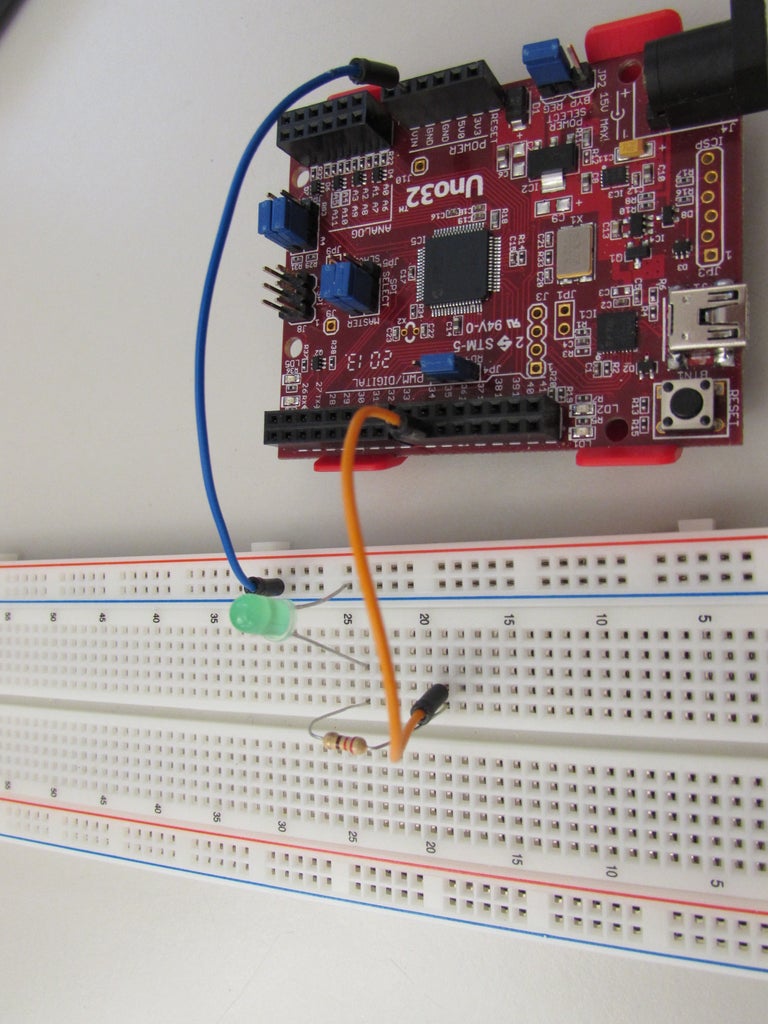
What is Pulse Width Modulation A Concise Overview Circuit Diagram A PWM, or 'pulse width modulation' signal is used to reduce the electrical power supplied to an electrical device by switching the signal on and off at a high frequency. As the relative on-time of the signal increases or decreases, so does the average voltage of the signal.

Basics of Pulse Width Modulation. It is a type of Pulse Time Modulation (PTM) technique where the timing of the carrier pulse is varied according to the modulating signal. The PWM pulse begins with the leading edge of the ramp signal and the width of the pulse is determined by the comparator circuit.

Understanding the Basics of Pulse Width Modulation (PWM) Circuit Diagram
The pin argument is the pin number where the pulse width modulation signal will be generated. The value argument is the analogWrite value that corresponds to the duty cycle of the pulse width modulation signal. To find the analogWrite value that will produce a pulse width modulation signal with a specific apparent voltage, use this formula:

Learn how pulse width modulation works and how to build a pulse width modulation signal generator with the 555 timer. Detailed instructions and schematics included. How to Build a Sawtooth and Triangle Wave Generator
How to Build a Pulse Width Modulation Signal Generator Circuit Diagram
Figure 1: pulse width modulation (PWM). The Practical Side of PWM. Enough about modulation theory, let's get a more practical view of what PWM really is. PWM is a technique which uses digital means to get an analog result. What's that mean? Let's use the example many of us are familiar with: driving a motor with PWM. Understanding the Basics of Pulse Width Modulation (PWM) Voltage can be changed by raising the series resistance within the electrical circuit, which in turn lowers the current through the motor. This change in voltage can be accomplished by series resistors, potentiometers, or rheostats. While these devices may be effective for small Pulse-width modulation, commonly known as PWM, is a modulation method that changes the pulse signal's width in electrical systems to regulate the average power supplied to a load. PWM is particularly helpful for effectively regulating the output of audio amplifiers, the speed of motors, and the brightness of light.
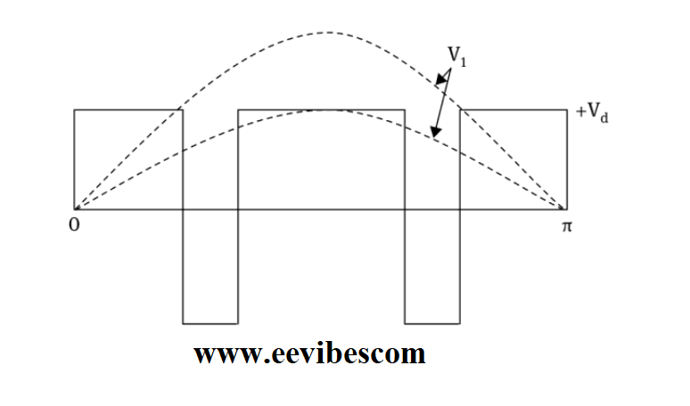
Now that we have the basics out of the way, let's build a circuit that will generate a pulse width modulation signal by using a 555 timer to switch a power MOSFET transistor. Here is the schematic: In the circuit above, we see a 555 timer configured as an astable oscillator. 1. What is Pulse Width Modulation? Pulse Width Modulation (PWM) is a technique for controlling the average output voltage by adjusting the duration of the high level of a signal (i.e., the pulse width). A PWM signal can be viewed as a series of square waves, where the duration of each pulse's high and low levels alternates in a certain proportion. So the current flowing through the circuit is flowing 80% of the time during the pulse width and no current flows through the circuit for only 20% of the time. If we further increase the pulse width to 100% you can see what's happened because the pulse width is 100% current is flowing through the circuit 100% of the time.
