What Is a Current Limiting Resistor Circuit Diagram To calculate the current limiter resistor, we will need to look at the figure below. The figure displays a variable resistor that you can use to set the current control. For the R1, you can replace it with a fixed resistor by calculating it with the indicated formula: R1 (limiting resistor) = Vref/current . Alternatively . R1 = 1.25/current Current limiting circuits are applicable in electronic circuits to restrict the flow of current through a load. They have various applications, including the following: Power Supplies : Power supply circuits often use current limiting circuits to safeguard their components from overcurrent situations. A fuse as well as a current limiting resistor both protect circuits however they work differently. A fuse is a safety device. If too much current flows, it breaks the circuit protecting the system. A current limiting resistor imposes resistance which restricts current, while when overloaded a current limit resistor does not break the circuit.

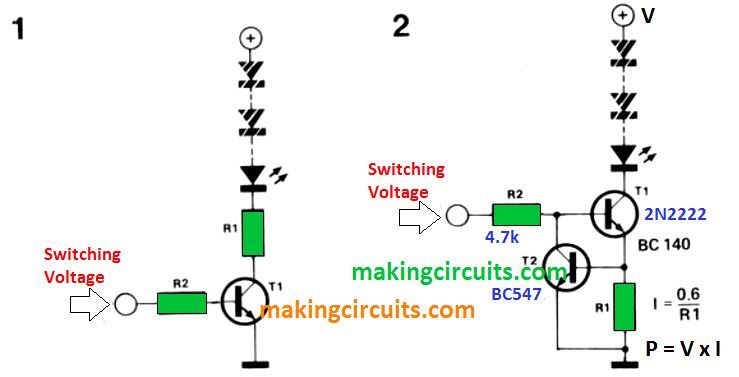
1- We want to design a current limiter and the maximum allowable current is 0.5 amps. We know that the base-emitter voltage (Vbe) of transistor T2 is 0.7 volts and the allowed maximum current is 0.5 amps. The resistor to be used, to achieve our goal is: R = Vbe / ILmax = 0.7 V / 0.5 Amps = 1.4 ohms. We can use a 1.5 ohm resistor.

Electronics Projects: How to Limit Current with a Resistor Circuit Diagram
Next, we need to use a suitable power of resistor. P = V x I. V = 6V I = the current of relay = 0.075A. So power of resistor is. = 6V x 0.075A = 0.45W We can use 82 ohms 0.5W resistor. Note: I taught my son to use this current-limiting resistor many years ago. and recently I taught my daughter this again. It is the basics that beginners
Some components, such as light-emitting diodes, are very sensitive to current. A few milliamps of current is enough to make an LED glow; a few hundred milliamps is enough to destroy the LED. Project 2-1 shows you how to build a simple circuit that demonstrates how a resistor can be used to limit current to an LED. SECTION 2: COMMON TYPES OF CURRENT LIMITING CIRCUITS There are several methods to implement current limiting in electronic circuits: H2 2.1 RESISTORS Resistors are the simplest form of current limiting devices. By placing a resistor in series with the load, the current flowing through the circuit can be limited. However, this method is not Since there is a 2 volt drop over the LED, there will be a 3V drop over the resistor. Ok, so we have 3V and we want to have 15 mA going through the resistor and the LED. To find the necessary resistor value we use Ohm's law. this gives us. So the necessary value for the current limiting resistor is 200 Ohms. Choosing the right resistor
Current Limiter circuit for Power Supply using transistor & resistor ... Circuit Diagram
Current limiting resistors are simple yet important circuit components that restrict current flow to safe levels in electronic systems. This guide provides a comprehensive overview of what current limiting resistors are, how they work, why we use them, how to select appropriate values and examples of their key applications.

In this video, Resistor as a current limiter, I've explained how to use a current limiter resistor and how to calculate the value of resistor._____