Transistor And Circuit Diagram In the previous tutorial we saw that the standard Bipolar Transistor or BJT, comes in two basic forms. An NPN (Negative-Positive-Negative) configuration and a PNP (Positive-Negative-Positive) configuration.That is: an NPN transistor and a PNP transistor types. The most commonly used transistor configuration is the NPN Transistor.We also learnt that the junctions of the bipolar transistor can This causes the transistor to act as an open switch, turning off the lamp. Note: In this circuit, we are using a digital input signal, but you can replace it with any DC signal. For example, it could be a push button connected to a DC power supply. How to Choose the Base Resistor. Bipolar transistors are controlled by the base current you apply.

Learn how transistors work as switches and amplifiers in circuits. See examples of NPN and PNP transistors, their symbols, leads and diagrams. PNP Transistor Switching Circuit . The equations for calculating the Base resistance, Collector current and voltages are exactly the same as for the previous NPN transistor switch. The difference this time is that we are switching power with a PNP transistor (sourcing current) instead of switching ground with an NPN transistor (sinking current Learn how to use transistors as electronic switches with this guide. See how BJT and MOSFET transistors work, how to choose them, and how to control them with circuits.

The Bipolar NPN Transistor Circuit Diagram
Learn how to use transistors as switches, amplifiers and sensors in simple circuits. See diagrams, symbols, currents, functional model and technical data for NPN and PNP transistors.
Transistor switches are critical circuit-building blocks; they're used to make logic gates, which go on to create microcontrollers, microprocessors, and other integrated circuits. Below are a few example circuits. Transistor Switch. Let's look at the most fundamental transistor-switch circuit: an NPN switch.
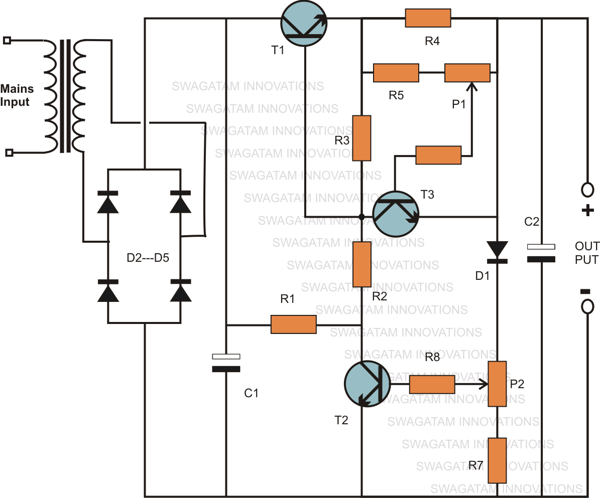
Build Simple Transistor Circuits Circuit Diagram
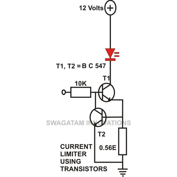
NPN Transistor Switching Circuit Diagram . Now as you see in the circuit diagram below, we made a voltage divider circuit using LDR and 1 mega ohm resistor. When there is light near the LDR, its resistances gets LOW and the input voltage at base terminal is below 0.7V which is not enough to turn ON the transistor. At this time the transistor The following single transistor circuit diagram is a variation of the aforementioned BFO idea, however it does not include a transformer secondary. When combined with a nearby radio receiver acting as a detector and amplifier, the circuit transforms into a basic metal object finder.

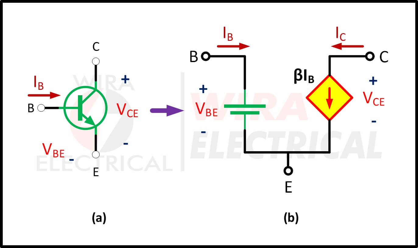
Learn how to analyze and design DC transistor circuits using equivalent models, current gains, and operation modes. See examples of common emitter, common base, and common collector configurations.