Solved Thermistors are typically used as temperature sensors Circuit Diagram A thermistor is a thermal resistor - a resistor that changes its resistance with temperature. Technically, all resistors are thermistors - their resistance changes slightly with temperature - but the change is usually very very small and difficult to measure. Thermistors are made so that the resistance changes drastically with temperature so that it can be 100 ohms or more of change per degree The diagram below shows an example of a temperature detection circuit block using an NTC thermistor. Fig. 8: Temperature control for thermal printers. but because the sensitivity of the sensor elements is temperature-dependent, a compensation circuit is necessary. The diagram below shows a compensation circuit with a combination of an NTC See this simple DC bridge circuit as shown in Figure 2 that is used for such precision measurement using the thermistor. A correct choice of resistors R 2 and R 3 will remove the mean DC value of ΔV. Figure 2. Temperature Measurement Using Thermistors . Considering this circuit, we now derive the relation between T and .V. In general, Assume
Therefore the B value will define the thermistors material constant between the range of T 1 and T 2.That is B T1/T2 or B 25/100 with typical NTC thermistor B values given anywhere between about 3000 and about 5000.. Note however, that both the temperature points of T 1 and T 2 are calculated in the temperature units of Kelvin where 0 0 C = 273.15 Kelvin. Thus a value of 25 o C is equal to 25
Adafruit Learning System Circuit Diagram
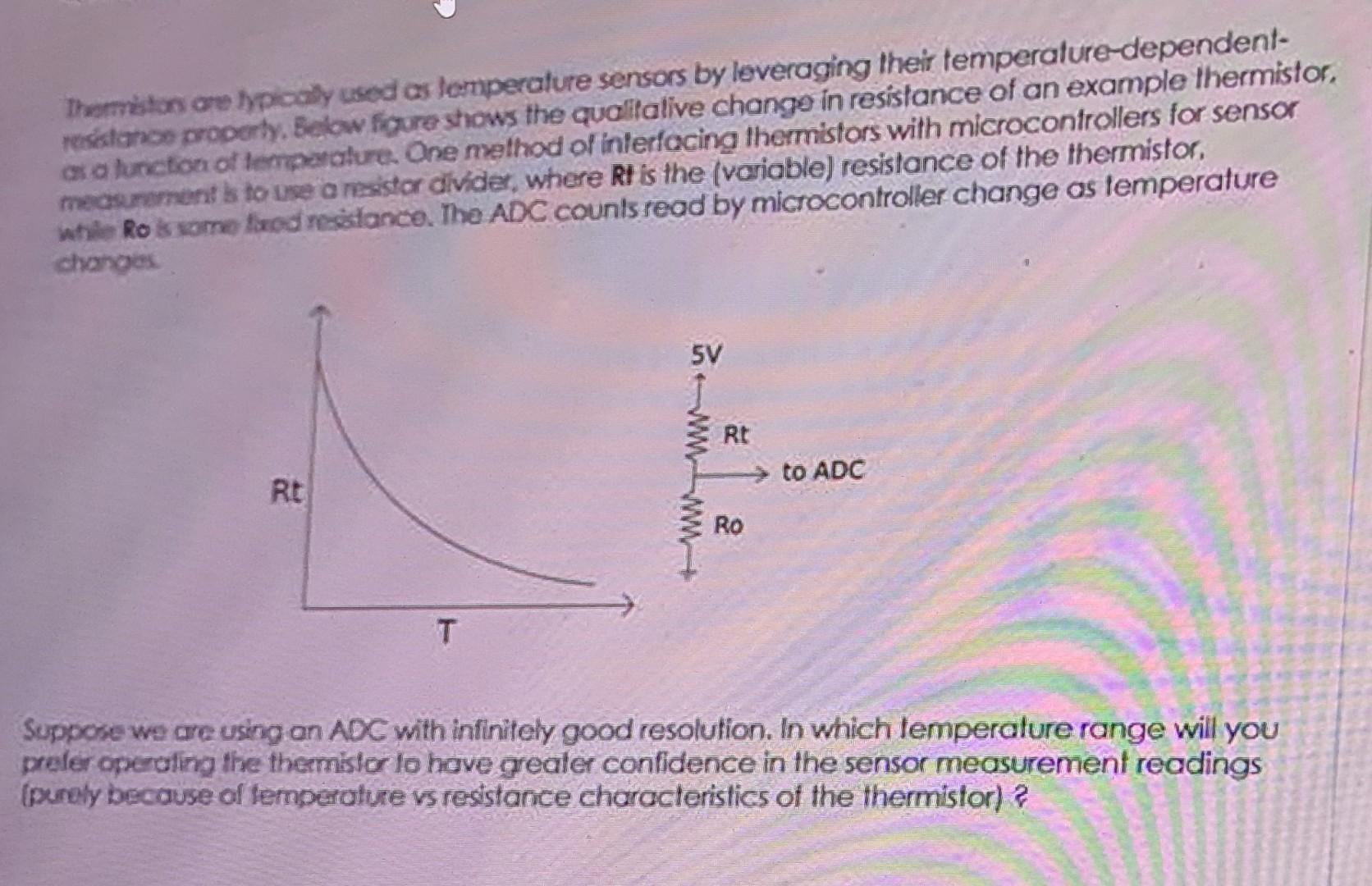
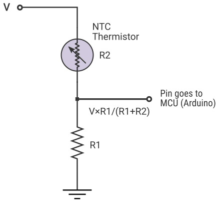
Use the thermistor and a reference resistor to make a voltage divider. Take the middle of the voltage divider and feed it into an analog-to-digital converter. Measure the ADC voltage in software. Using your knowledge of the reference resistance, and the thermistor's R vs. T curve, convert from ADC counts to temperature.
Very Simple Temperature Indicator using a Meter. The following post explain how to build a simple temperature indicator using a 1 mA moving coil meter and a few transistors and resistors. The sensor device in this project is the diode 1N4148. How it Works. In the above temperature meter circuit, a 1N4148 diode is employed to sense the temperature. Bead thermistors have a faster response time vs. radial/SMD thermistors. However, they are not as robust. So, the thermistor type to use depends on the end application and the environment in which the thermistor will reside. The long-term stability of a thermistor is dependent on the materials it is made from along with its packaging and
How to measure temperature using a NTC thermistor? Circuit Diagram
These thermistors are widely used for temperature measurement and compensation in various industries and electronic devices. Working Principle of NTC Thermistor. The working principle of an NTC thermistor is based on the temperature-dependent behavior of its electrical resistance. As the temperature increases, the number of charge carriers in

Temperature compensation (i.e. maintain resistance to compensate for effects caused by changes in temperature in another part of the circuit) Used in wheatstone bridge circuits; How Does a Thermistor Work. The working principle of a thermistor is that its resistance is dependent on its temperature.