Signal Processing Circuit Diagram 1) Using IC 4049. Using only one low-cost CMOS IC 4049 and a handful of separate modules, it is easy to create a robust function generator that will provide a range of three waveforms around and beyond the audio spectrum.. The purpose of the article was to create a basic, cost-effective, open source frequency generator that is easy to construct and used by all hobbyists and lab professionals. This circuit features a simple thyristor signal generator employing a single thyristor, two resistors, a capacitor and a miniature loudspeaker.. When the circuit is activated by a current source current passes through R1 activating the thyristor.. The thyristor then conducts current charging capacitor C1. As the charging current decreases inversely with the capacitors charging, it gradually
- Tied a signal mode to CHANnel; so, now you may change signal form along with the frequency. - Slightly changed navigation. - Use EEPROM to store and recover settings. - Added a new signal mode: square/meander signal wave at 1/2 frequency (for even more accuracy of the output signal frequency). This is a standard feature of AD9833 module. Learn how to make a square wave signal generator. With step by step instructions on how to calculate and change the frequency of the square wave. How to Build Audio Filter Circuits. Graham Lambert 3 6 min read. Learn how to build four different audio filters - high-pass, low-pass, band-pass, and notch filters. Detailed instructions and The output level of the sine wave signal is around 500mV RMS. 3) Using Audio Amplifier LM380. The circuit is built around an audio power amplifier device (IC1) utilized in a phase shift oscillator circuit. A three-section phase shift circuit is used to provide feedback between the output and the inverting (−) input of IC1.
How to Build Your Own Function Generator Using Analog Devices' AD9833 Circuit Diagram
Creating an audio signal generator circuit diagram may seem intimidating and complicated, but with a little bit of knowledge and some practice, anyone can gain the skills necessary to get it done. By following this guide and understanding the basics, it's possible to create your own audio signal generators and reap the many benefits they can offer.
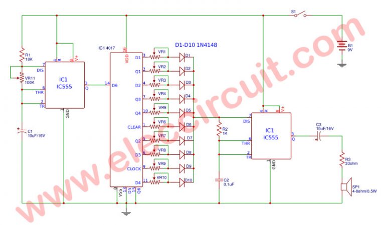
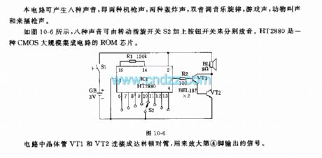
This audio frequency generator is a triggered signal generator. When a positive pulse of about 6 volts (minimum) is fed to the circuits input , a modulated audio signal comes out of the output. The signal pattern is similar to a bird's chirp. The pulse width of the trigger signal must be a minimum of 2.5 miliseconds. Working Explanation. The operation of this circuit is based on the working principle of a self-triggering oscillator (astable multivibrator), performed by a 555 precision timer circuit (NE555).When the circuit is powered on, The values of resistors (R1, R2) & capacitors (C1, C2) on the left side of the circuit set the pitch of the output tone coming from the audio transducer (loudspeaker Pulse Generator And Signal Tracer Circuit Diagram. This simple circuit generates narrow pulses at about 700-800Hz frequency. The pulses, containing harmonics up to the MHz region, can be injected into audio or radio-frequency stages of amplifiers, receivers and the like for testing purposes. A high-pitched tone can be heard from the speaker of
