Peltier Cooler Circuit Diagram Introduction: Mini Peltier Air Conditioner (Plans) By ASCAS Follow. This machine uses a Peltier Module as a cooling mechanism and some cooling fans for blowing air. Step 1: Here Is a Picture How It Works. This is just like the everyday air conditioner that we use. The only thing unique about this that the cooling unit has no moving parts. This TEC1-12706 module and the Peltier effect makes the perfect DIY cooler! This instructable is a step-by-step tutorial showing you how to make your homemade cooler. This DIY fridge uses the Peltier effect, which is the presence of heating or cooling at an electrified junction of two different conductors. ️ Want to build your own cooling system? Learn how to assemble a Peltier cooler kit and make a DIY Peltier air conditioner at home! This step-by-step guide

#unboxing peltier #thermoelectric module assembly #peltier kit assembly🔸(Available now for best prices) Buy peltier module here: https://amzn.to/311STA9 Buy However, challenges Peltier cooling technology faces is efficiency and limited temperature differences. By now, the efficiency of Peltier cooling is only around 5% or so, which is lower than compressors. In the near future, Peltier effect will mainly be adopted on small or portable devices considering its small size and simple components. A Peltier Module (TEC1-12706) with wires attached. Now you can build yourself a mini Refrigerator using the Peltier devices and a few other simple components. Peltier effect modules can also be used for temperature control for applications like cooling in electronic devices, circuits, and systems where a low budget and lightweight cooling

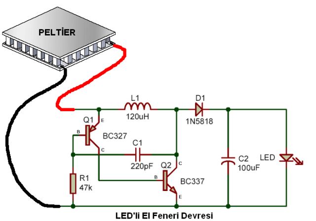
How to Set Up a Peltier Module. : 6 Steps Circuit Diagram
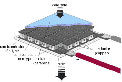
A sensor will control the alimentation by turning the Peltier module on and off, depending on the settings. Check the wire diagram at the end of this post to see how to connect everything to the Peltier device and the power supply. The TEC-12706 Peltier module can in theory use up to 6 amps, so it needs a good power supply. To use a Peltier module in a circuit: Identify the hot and cold sides of the module. Connect the positive terminal of the power supply to the positive (V+) pin of the Peltier module. Connect the negative terminal of the power supply to the negative (V-) pin of the Peltier module. Apply the appropriate voltage as per the module's specifications.
