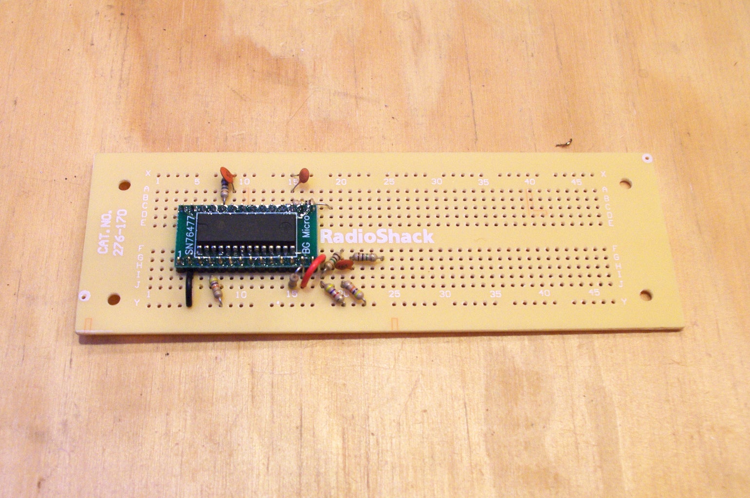
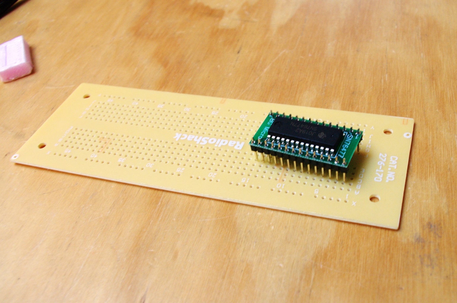
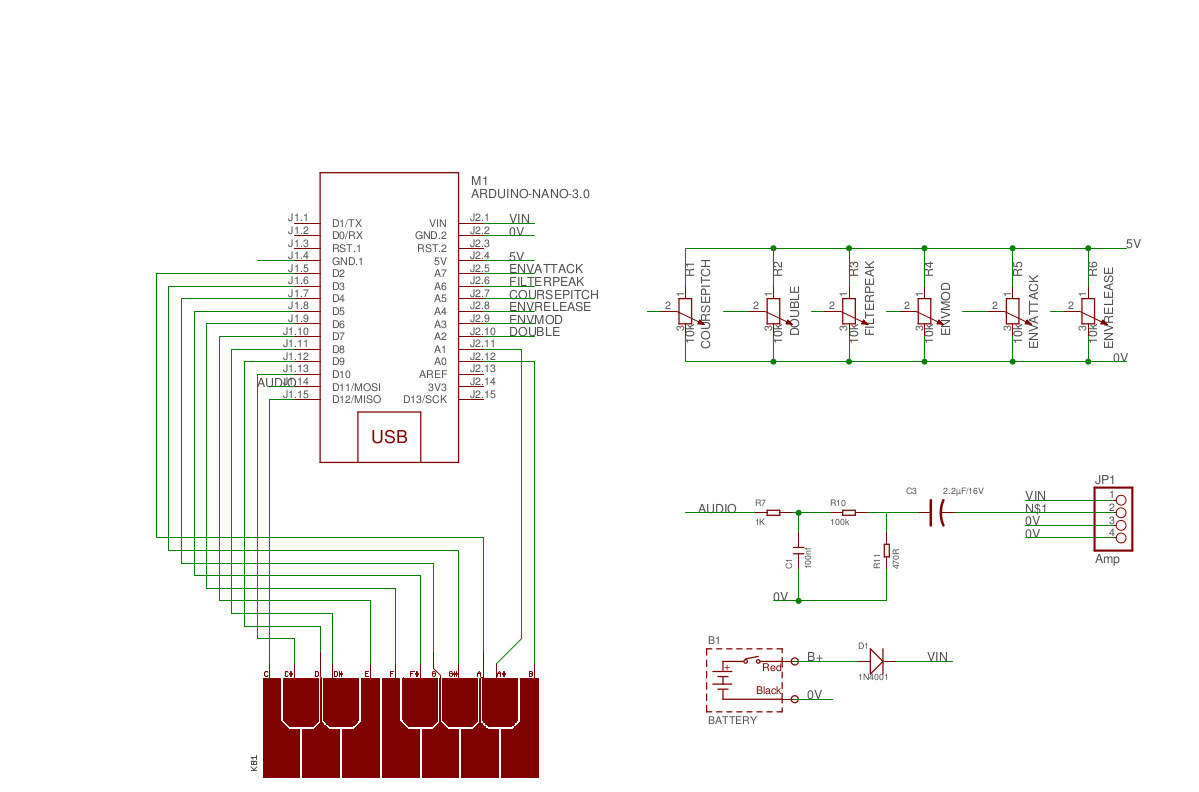
My First Synth 29 Steps with Pictures Circuit Diagram By using a breadboard to build the circuit first, it is much easier to transfer the circuit to your Protoboard later. Run wires from the GND and 5V to the - and + rails of your breadboard. Then, connect the signal wires from the potentiometers to Analog Input 0-4 on the Arduino. Cheap, noisy, and easy to build, the Atari Punk Console is one of the most popular DIY synths for beginners. The circuit (originally called the "Sound Synthesizer" and later, the "Stepped Tone Generator") was first published in a 1970s Radio Shack DIY booklet, but is now sold in kit form by many vendors. For some really thorough and beginner-friendly explanations of DIY synthesizer circuits, subscribe to Moritz Klein. The Audiophool covers similar material, but in a more bite sized format. Look Mum No Computer aims more at entertaining the audience, but there is still plenty to learn here too. The host Sam Battle is a natural showman with a
Analog synthesizers are very cool, but also quite difficult to make. So I wanted to make one as simple as it can get, so its functioning can be easily understandable. For it to work, you need a few basic sub-circuits: A simple oscillator with resistor selectable oscillating frequency, some keys, and a basic amplifier circuit. Normally, the circuit will be open at the node between the 25-resistor series and pins 2 and 6 of the 555. Hooking up these two pins to a stylus allows us to dynamically close the circuit by touching the stylus to one of the copper pour pads. Each pad will act as an individual music key when the project is complete. Frequency Tuning
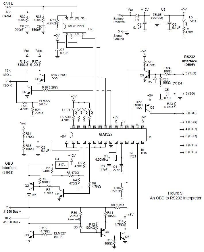
The Arduino Synthesizer : 20 Steps (with Pictures) Circuit Diagram
This week I tried (somewhat successfully) to design and build a basic music synthesizer circuit and found a ton of gaps in my knowledge along the way. So I thought I'd share and maybe you'll start experimenting with synth circuits too! In this post we'll cover my initial design and what I learned along the way, so without further ado…
Simple 555 Piano. source: circuit.io . Light2sound LDR Synth breadboard schematics, source: makezine.com . Polyphonic 4093 NAND Synth breadboard schematics, source: digital.music.cornell.edu . Make an Arduino synthesizer! You can make it using breadboard os special Arduino shield. Most of you work will go into programming, but still, no

how to start? Circuit Diagram
The 555 chip has to be one of the most iconic integrated circuits of all time and is a very popular part with both hobbyists and engineers alike. In this project, we will create a funky synth that is based on a popular circuit called a stepped oscillator (also known as an Atari Punk Console). Synthesizer Type and Music Theory. The synthesizer that we will be designing was extremely common back in the day. It's known as a 1V/Octave synthesizer. This means that for every 1V increase on the input, the output frequency will go up by one octave (i.e., by a factor of 2). The difference in circuit i build is first of all i'm using

Build The Circuit. Here's how you can connect this circuit on a breadboard: There are a lot of connections that need to be right in order for the 555 Timer Music Box to work. I recommend building and testing the circuit in stages. First, build the first 555 timer circuit, and check that it gives a reasonable beat to set the tempo.