LED Matrix Display Circuit Diagram be selected according to the specific system requirements. Therefore, circuit #3 is adopted in this solution. 2.3 Step 3 - Ghost Cancelling Ghost is a common phenomenon in time-multiplexed LED-based matrix displays. Since PN junctions of LED lamps have relatively high levels of capacitance, their residual charge can keep triggering capacitive
MAX7219 Module Overview. The MAX7219 module is a popular choice for controlling LED matrix displays, and it comes in different variations. Among them, two widely used types are the generic MAX7219 module and the FC-16 module.While both serve the same fundamental purpose, there are slight differences in their design and pin configuration, making it essential to choose the right module based on

Arduino Tutorial - Arduino Getting Started Circuit Diagram
Figure 5: Arduino Uno 5x7 LED matrix display driver circuit The matrix display used in the example circuit is a CCAR display. It comes in a 14 pin package (figure 6). The pins are aligned in two rows. One at the top and the other at the bottom of the package. Pin 1 is the first pin on the left of the bottom row. Figure 6: LED matrix display Learn how LED matrix works, how to connect LED matrix to Arduino, and how to program Arduino step by step. Detailed instructions, code, wiring diagram, video tutorial, and line-by-line code explanation are provided to help you quickly get started with Arduino.
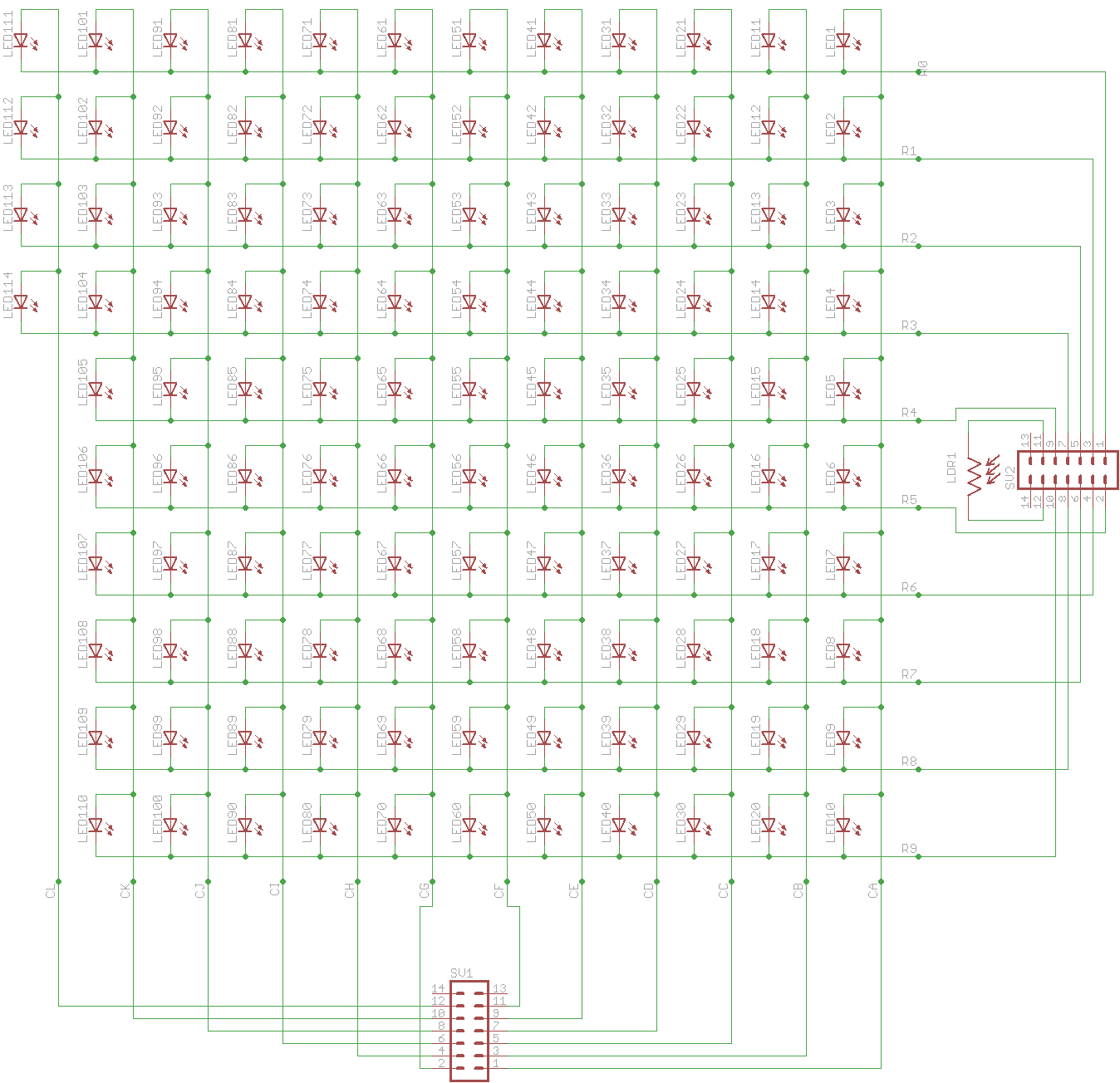
The circuit diagram of the 7×5 LED matrix display using Arduino is shown in figure 1. The entire circuit of LED matrix is built around Arduino uno board, few NPN bipolar junction transistors (7 nos. in 7×5 display), a few numbers of resistors (equal to the number of transistor i.e. 7), and LEDs (7×5 = 35 nos.). Upload the program to the Arduino and power up the circuit. The LED matrix display should show a colorful rainbow pattern cycling through the LEDs. Adjust the code and experiment with different patterns and colors. Conclusion. Building a colorful LED matrix display with WS2812B modules allows for creating dynamic lighting effects and visual This circuit features an ESP32 microcontroller connected to a 32x8 WS2812 LED matrix. The ESP32 controls the LED matrix through a 220-ohm resistor connected to its D12 pin, providing data input to the matrix, while power and ground connections are shared between the ESP32 and the LED matrix.

Arduino and MAX7219 Dot Matrix Display A Complete Guide Circuit Diagram
This circuit features an Arduino UNO microcontroller connected to multiple 8x8 LED matrix displays and pushbuttons. The pushbuttons are interfaced with digital pins D2, D3, and D4 on the Arduino for input, while the LED matrices are connected to digital pins D5 through D10 for control signals.