IoTEnabled Smart Agriculture Circuit Diagram Experience the future of farm automation with our smart switch system. Simplify your operations, enhance productivity, and embrace a more streamlined approach to agricultural and industrial work. Say goodbye to manual constraints and embrace the power of innovation with our smart switch solution. Smart Agriculture System Circuit Diagram. The complete schematic for the Smart Agriculture System is given below:. This circuit isn't that hard. Here we have used 4 sensors i.e. DHT11, DS18B20 sensor probe, LDR and Soil Moisture Sensor, one 12V LED Strip, 12V water pump, 7805 voltage regulator, and two TP122 transistors to control Led strip and water pump. 7805 is used to get the regulated In this project, we are going to build a Smart Farming System using IoT. The objective of this project is to offer assistance… Sensing the Future of Smart Agriculture with Arduino Edge Control. Arduino Pro has released Arduino Edge Control, a smart remote solution for monitoring and control for deploying AI on the edge…
Smart Agriculture Components. Soil moisture level monitoring. Circuit . Power Supply Connections. DC Jack: This connects to the 12V battery. It powers the entire circuit, including the pump, microcontrollers, and sensors. Uses "automation" to control the pump based on the inputs from the soil moisture sensors. Smart Home-Agro System focuses on developing an intelligent agricultural system that can perform and even monitor various farming tasks. With a Smart home-agro system, we can schedule the system to irrigate a piece of land (Home garden) automatically or spray fertilizers(or pesticides) on the crops wirelessly through our smartphone. The shown application note is intended to replicate a scaled smart farming application, that can be implemented on real agriculture fields using the same hardware and firmware. Goals. The goal of this application note is to showcase a smart farming irrigation system using a combination of an Edge Control, an MKR WiFi 1010, and the Arduino Cloud.
Smart Farm Irrigation System Using Arduino® Edge Control Circuit Diagram
IoT Based Smart Agriculture & Automatic Irrigation System with NodeMCU ESP8266, Capacitive Soil Moisture Sensor, DC Water Pump, Relay Code Hence the method is making agriculture smart using automation and IoT technologies. Internet of Things If you don't want to assemble the circuit on breadboard and you want PCB for the project, then

soon as possible. To improve visual feedback, the circuit additionally incorporates basic status LEDs (D9, D10, and 3.2. Circuit Operation ittached to digital pin D2 emits an auditory signal, guaranteeing that farmers are informed of critical conditions as The Smart Agriculture System's response is visible and understandable thanks to the thoughtful placement of the LED components. Block diagram of the low-cost smart agriculture system is shown in Fig. 1. The author's prototype of the project is shown in Fig. 2 while its circuit diagram is shown in Fig. 3. Fig. 1: Block diagram of the smart agriculture system Fig. 2: Author's prototype for smart agriculture system Fig. 3: Circuit diagram of the smart agriculture system

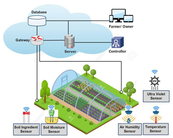
IoT based Smart Agriculture Monitoring System Circuit Diagram
MPLAB® ICE 4 In-Circuit Emulator; MPLAB® PICkit™ 5 In-Circuit Debugger; farmers are adopting smart agriculture technologies like IoT, AI/ML, advanced sensors, microprocessors (MPUs) and microcontrollers (MCUs) to optimize resources, enhance crop quality, ensure security and boost profitability. Automation in Smart Agriculture; View