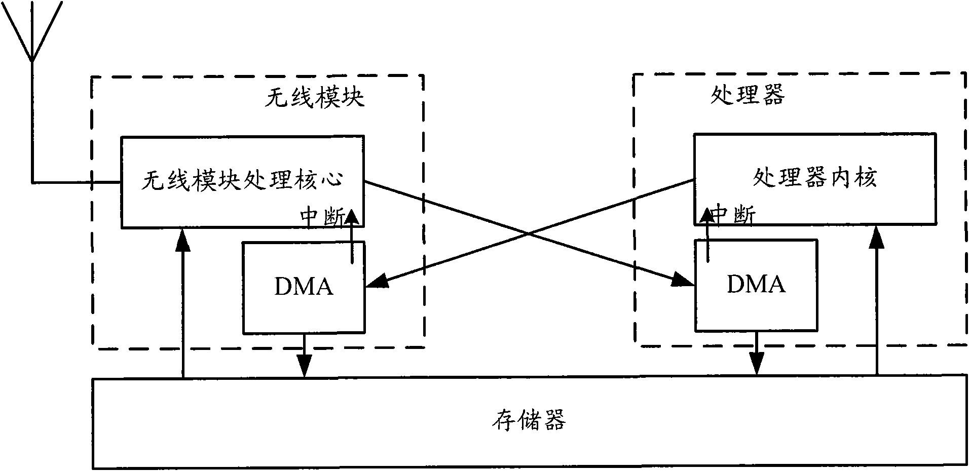
Implementation of a wireless data transmission path Circuit Diagram Wireless Systems and Core Components. Wireless communication systems rely on a precise interplay of transmitters, receivers, and antennas to transmit and interpret electromagnetic waves. These components form the backbone of wireless technology, enabling everything from basic radio broadcasts to modern high-speed networks. The rest of the chapter is organized as follows: Sec. 2 summarizes related works on real-time wireless communications technologies. Sec. 3 provides an overview on 802.11 WLANs and RTOSs, as basic elements to realize a wireless real-time system. In Sec. 4, the architecture of a WNCS is described and its performances are evaluated in Sec. 5.
It is shown that the introduction of channel coding blocks into GNU Radio-based OFDM system reduced the PFR of data signals transmitted over Universal Software Radio Peripheral (USRP) boards. The term "Software Defined Radio" (SDR) has become familiar in research and development of wireless communication systems today. SDR allows users to adjust a system with its flexibility and re The document describes a project report on wireless power transfer submitted by a student for their Bachelor of Technology degree. It includes a cover page, certificate from the project guide, acknowledgements, declaration, table of contents, and sections describing the abstract, block diagram, hardware requirements including various electronic components, schematic diagram, hardware testing communication where one II.has to transmit data while the other needs to receive for the operation. The problem becomes evident if the systems are at a very larger distances. So we need to go for wireless communication. a A software defined radio is a reconfigurable radio whose physical layer functions are mainly or fully defined

world Transmission with GNU Radio and USRP Circuit Diagram
Each measurement point is made by a sensor node (ZigBee) and a GPS receiver coupled with three axial accelerometers for real-time data collection and transmission. The wireless data acquisition system adopts omni-directional antennas with a high gain of 5.4dBi, but the communication range can be extended. However, a higher gain will lead to Then, input benchmark_tx python file with proper parameters setting (./benchmark_tx.py -f 900M) in transmitter side. You will see the data transmission with packet number and CRC result output from the command line. -- Thank Chris for his voice recording! Experiment 2: Voice transmission. Figure 3: system diagram for voice transmission
With the needed libraries included, we now create a RH_ASK object to send and receive data with. The RH_ASK object declaration accepts several parameters. If no parameters are passed, then the default options are assumed, but it is best to set at least the first three as these define the speed of the radio transmission, the tx pin, and the rx pin. The data can be acquired from a physical system either by a wired or a wireless connection. Today we will see the first one. Now to acquire the data we need a sensing element that can read the physical parameters and then process and covert that data into digital form. This data will then be sent using the Serial port of the Arduino.
time COFDM transmission system based on the ... Circuit Diagram
Ultra-reliable and low-latency communication (URLLC) is promising to enable real-time wireless control systems for tactile internet. In such a system, it is difficult to maintain extremely high quality-of-service (QoS) in URLLC for real-time control. In this paper, we develop a probability-based device-to-device (D2D) scheme to deal with this issue, where communication and control are jointly
