How to Use Digital Potentiometers to Control Light and Sound Circuit Diagram It also makes the circuit diagram a little bit nicer-looking I think. Wiring Example #3: Potentiometer as Volume Control. This example uses all three pins of the potentiometer to create a simple way of adjusting the volume of an audio amplifier.

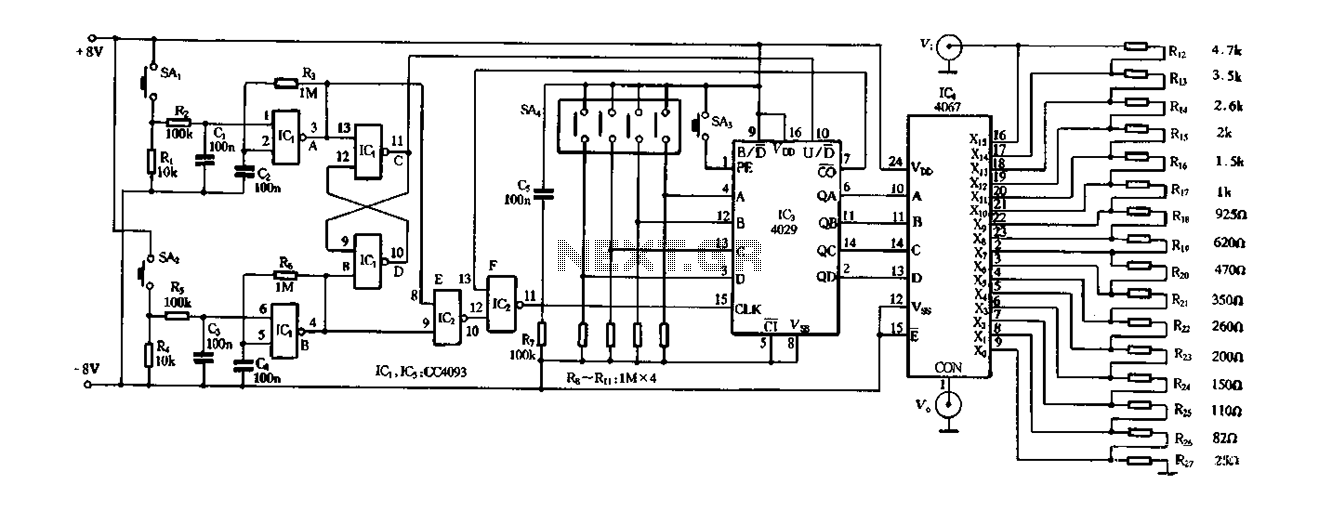
This design of digital POT is considered as an illustration of linear taper. The total number of steps in this resistive ladder defines the resolution of the device. The below picture shows the digital potentiometer circuit diagram in ladder design. The digital resistors are regulated through up/down signals or by protocols like SPI and I 2 C.
Digital Potentiometer : Circuit, Working, Types and Its Applications Circuit Diagram
A digital potentiometer serves the same function as a potentiometer in hardware in that it varies resistance output. The difference is a digital potentiometer IC is controlled by software, while a regular potentiometer is controlled manually by a person. Just like a regular potentiometer, a digital Pot IC comes in all different values of the digital potentiometer. RAB is the nominal resistance across the entire potentiometer, from pin A to pin B. RBW is the resistance between pin B and pin W of the digital potentiometer. n is the number of digital potentiometer bits. For the MCP4XXXX family of potentiometers, the number of bits is eight. Dn is the digital code in decimal form
In this second design we investigate the IC X9315 which is actually a solid state digital potentiometer and could be used exactly like a mechanical potentiometer, but through logical supply inputs. The IC X9315 from Intersil, is a digitally controlled solid state potentiometer, which internally possesses an array of resistors, wiper switches, a The digital potentiometer (digipot) is a processor-controlled, • The required resistance value, often called end-to-end resistance, is determined by the design considerations of the circuit. Vendors offer resistances between 5 kilohms (kΩ) and 100 kΩ in a 1/2/5 sequence with some other intermediate values.
Digital Potentiometer Fundamentals Circuit Diagram
Digital potentiometers find applications in various electronic systems, including audio equipment, instrumentation, programmable voltage and current sources, motor control, and calibration circuits. They offer flexibility, versatility, and improved functionality compared to traditional potentiometers, especially in scenarios where precise A potentiometer is a variable resistor that can be used in a circuit to control resistance, current, and voltage through a circuit to attain a certain output, we already know the basics of Resistor and how they work. The potentiometer is just a variable resistor, sometimes also called a rheostat, which you all could have seen in your physics laboratory, it consists of a metal coil wound on a The typical potentiometer will have 3 pins, two power supply pins (+5V and GND), and one pin that connects to an analog input pin on your Arduino to read the value output. To learn how to read data from a potentiometer, and display it in the Serial Monitor, visit the Analog Read Serial example. Hardware Required. Arduino board; Potentiometer
