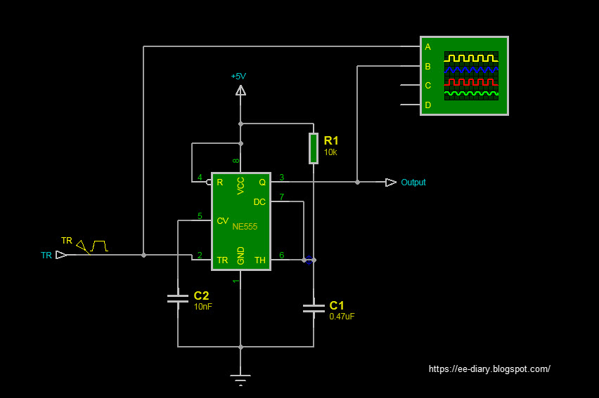
How to simulate 555 Timer as Monostable Multivibrator in Proteus Circuit Diagram This circuit is using a simple approach to make an adjustable sound generator using 555 IC. You all must be aware of the fact that the 555 IC is the most versatile and famous IC in the world of Electronics. This IC provides an oscillation frequency ranging from 670 to 680Hz. In this circuit, we are using this as an astable multivibrator.

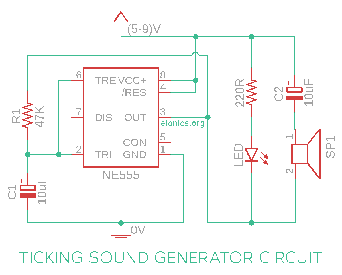
Learn: How to use 555 timer circuits. 555 Sound effect Metronome circuit. We have many ways to build a metronome circuit. First, using transistor so easy way and cheaper. But now I try IC-555 timer. It also easy and drive a speaker directly. Even can emit two sound effect metronome. It is hard that I tell you. Sometimes you have to build it A tutorial on how to make a ticking sound generator circuit using 555 timer IC. The sound feels similar to the one used when showing a ticking time bomb in movies. A reverb container can be added over the speaker to make it sound similar to the tick tock audio emanated from mechanical clocks.

555 Tone Generator : 10 Steps (with Pictures ... Circuit Diagram
This simple project can be used to generate sound which can be heard through a speaker or a buzzer by connecting either of them to its output. The idea is to [[wysiwyg_imageupload::]]generate a frequency in the audible range from a normal pulse generator. Using the circuit in a battery saving mode so that it can work for a longer duration is made possible by using a 555 IC. This IC is known to The task of this sound generator circuit is to give a frequency output which lies in the audible range of a human being, i.e in between 20 and 20,000Hz. Sound is generated in this circuit by using two 555 timer IC's. The other components required in this project, along with the two ICs are few resistors and capacitors, one diode, 12 Volts DC power supply, and a speaker.

This sound generator circuit uses the 555 timer IC to produce a monotone sound of 800 Hz that could be used as the basis of an alarm system. In this circuit, we are using the 555 IC in astable configuration to produce a train of rapidly changing square waves. Each square wave will cause the speaker cone to move up and then down (very fast), and therefore it will vibrate rapidly creating sound

Ultrasonic Sound Generator using 555 Timer Circuit Diagram
Hi, I am Electroni and in this video i show you how to make simple tone generator using common 555 timer chip. This circuit can make any frequency of sound.L Such periodic signals produce a beeping sound when connected to audio transducers such as a speaker, piezo, etc. Simple Tone generator circuit using 555. The below circuit consists of an astable multivibrator using a 555 timer IC. It generates a continuous square wave output. The circuit has an oscillation frequency about 670-680 HZ. The SOUND FORGE is a 555 timer-based music box that uses a few lever switches and potentiometers to produce and modify sound. Here, we have created this device by slightly altering an old 555 mouth organ circuit. In monostable mode, the Timer IC is connected to four potentiometers, four lever switches, and an output speaker that is one ohm.
