How to Properly Wire a GPS Speedometer Detailed Diagram and Instructions Circuit Diagram If you don't want to use a GPS to measure speed you can also build a speed sensor using IR sensor and Arduino, which is much more simple and easy to build, but it can measure speed only at fixed points. In this project, we will build an Arduino GPS speedometer using a NEO6M GPS module with an OLED display. Materials Used. Arduino Nano; NEO6M DIY GPS Speedometer Using Arduino and OLED Display | Step-by-Step TutorialWelcome to our detailed tutorial on creating a GPS speedometer using an Arduino, an

The project I made this time is the GPS Speedometer Application with ESP32-S3 (WT32-SC01 Plus).A speedometer is a tool that indicates the speed of a vehicle.
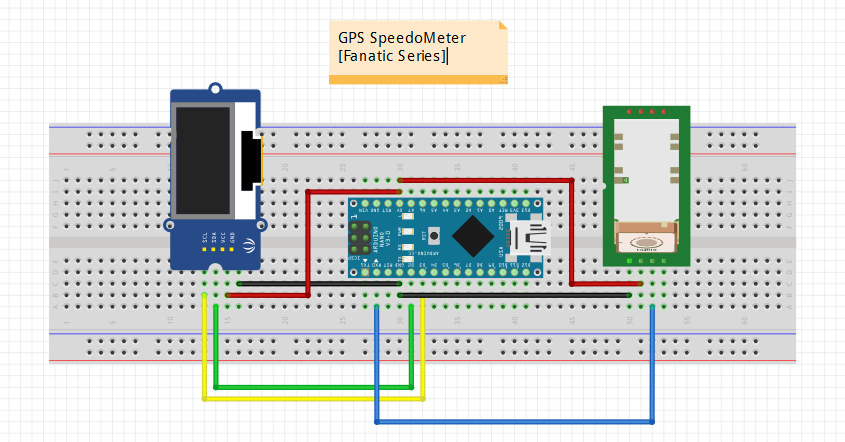
Let's build a GPS Speedometer with ESP32 Circuit Diagram
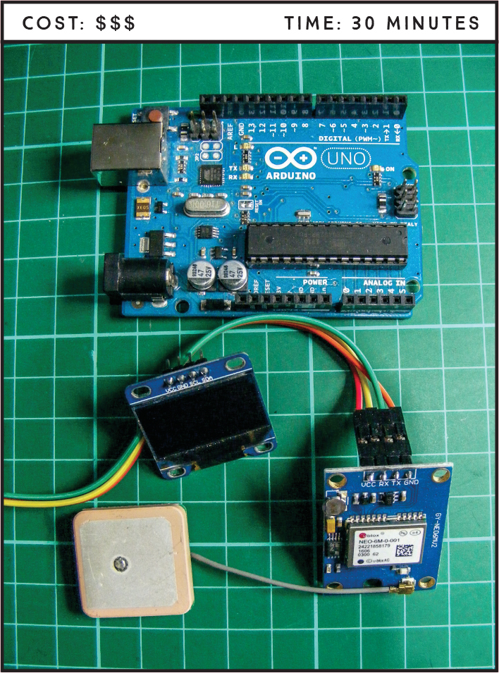
This presented like a good opportunity to build a new project, "The GPS Speedometer". Of course the ideal solution would be, really repair the car or use a normal GPS or use an app with this function but what would be the fun in this :) Step 1: Components. Microcontroller.
NEO 6M GPS Module. For the Speedometer project will be using the NEO-6M GPS V2 module.The NEO-6M is a popular GPS receiver that has a built-in ceramic antenna, it offers useful satellite search capabilities.With the ability to track up to 22 satellites, it provides accurate location coordinates of your position in the world.. The onboard signal LED indicator will help to monitor the GPS This post shows how to make a DIY Arduino speedometer using an analog gauge and a GPS module. The gauge is used to display the current speed, while the GPS module is used to track the speed in real-time. this project combines an Arduino board with a GPS module to display real-time speed on a classic analog gauge. Register and get $100 from NextPCB: https://www.nextpcb.com/register?code=HtoeletricPCB Assembly capabilities info: https://www.nextpcb.com/pcb-assembly-serv

DIY GPS Speedometer with Arduino and OLED Display Circuit Diagram
//data was not updated for some time, assume that GPS connection is lost. iSpeed = 0;} else {//GPS connection is up to date, get the speed information, and round it to closest integer value. iSpeed = round(gps.f_speed_kmph()); // speed in km/h} //when not moving, the GPS module will still read some "speed" value, not necessarily zero In order to build a GPS Speedometer, we need a GPS Receiver. The most popular GPS Receiver is ublox NEO-6M GPS Module. But we will use Quectel L86 GPS Module as it is tiny with a very small antenna. By interfacing L86 GPS Module with Arduino and 0.96″ OLED Display, the speed related parameters can be displayed on OLED Screen. Arduino Speed Detector Circuit Diagram. A simple breadboard based circuit diagram is shown below to help you with making the connections. As you can see the circuit is very simple and only consists of two IR sensors, an Arduino Uno, LCD display and a breadboard. Also note that, to power this circuit you will need an external 12V power adapter.