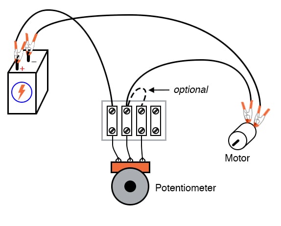
How a Potentiometer Works And How to Use with Arduino Full Guide Circuit Diagram We use potentiometers as voltage dividers or current limiters. With a voltage divider, we connect the power supply across the two end pins, and the wiper connects to the centre pin. This pin provides our output voltage. We can also use potentiometers for current control, we call this a rheostat. Potentiometers only have a small power rating
Potentiometer - How to lower voltage using variable resistor (pot) As voltage divider This video is about potentiometer. In this video I will show you the us
The Potentiometer: Pinout, Wiring, and How It Works Circuit Diagram
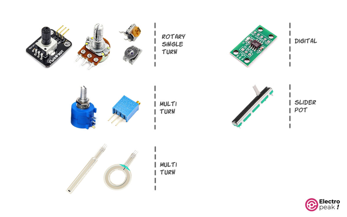
The output voltage will be taken across any one of the two input terminals and the sliding contact. The POT helps us to use variable voltages in the same device. Different Types of Potentiometers. The Potentiometer or POT is manufactured by using different types of materials like carbon composition, cermet, metal film, and conductive plastic. Wiring Example #3: Potentiometer as Volume Control This example uses all three pins of the potentiometer to create a simple way of adjusting the volume of an audio amplifier . By connecting it like this, you'll get a voltage divider that decreases the voltage of the input signal.
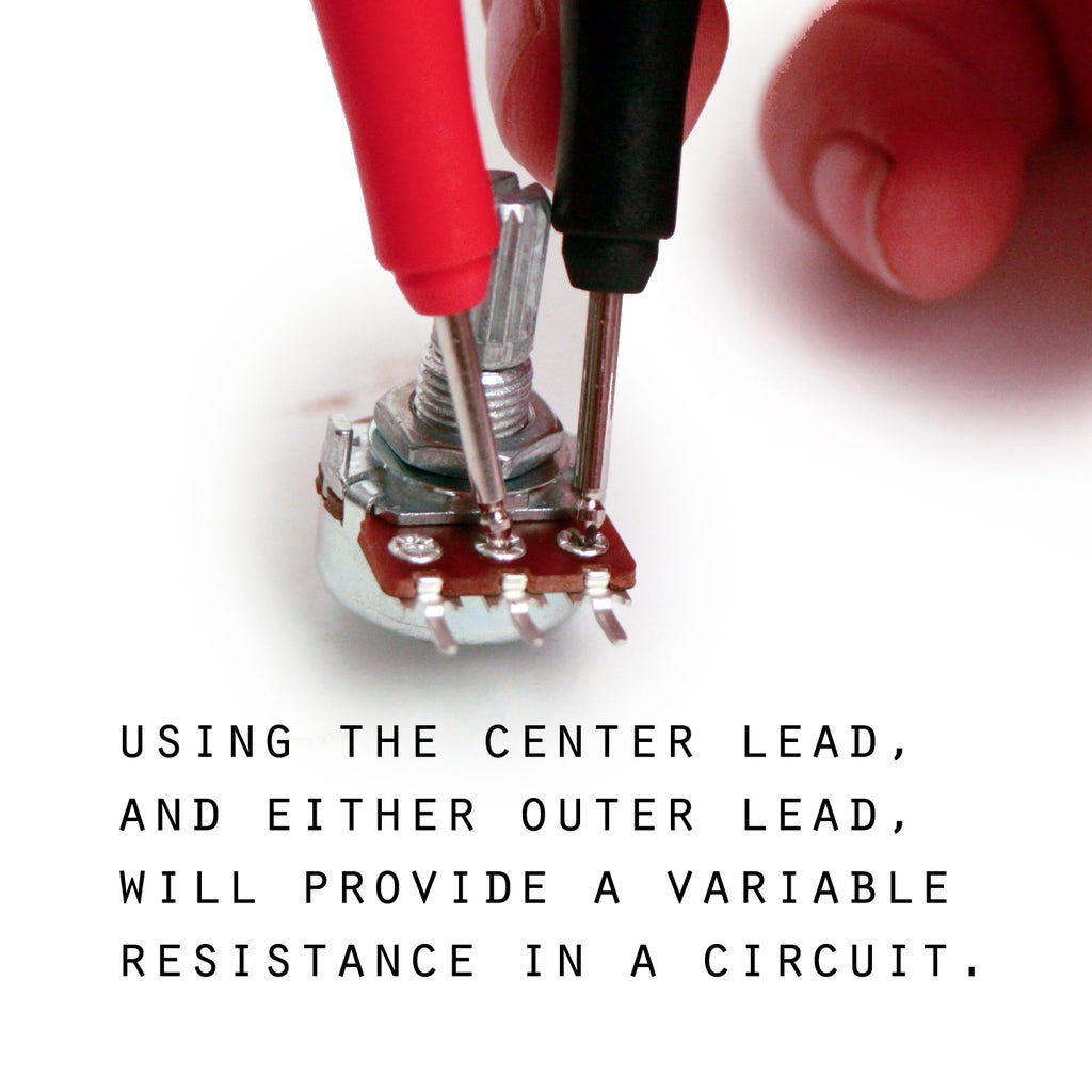
The shaft is connected to the wiper. Using one of the end terminals and the wipers, create a variable resistor to control or adjust current. Use all three terminals to create a voltage divider to control or adjust voltage. The following exercise illustrates how to wire a potentiometer to control voltage and current. A potentiometer is a three-terminal variable resistor that allows for adjustable voltage division in an electrical circuit.It functions by varying the resistance along its length, providing a way to control the output voltage. The main components of a potentiometer include the resistor body, wiper, and terminals.

The (Complete) Engineers Guide to Potentiometers and How to ... Circuit Diagram
Set up the Voltage Divider. Remember to GROUND the potentiometer. Forgetting to ground the POT seems to be the common mistake. 3.) Place the LED and current limiting resistor on the board. Basic Red LEDs - This is a very basic 5mm LED with a red lens. It has a typical forward voltage of 2.0V and a . rated forward current of 20mA. Features: \$\begingroup\$ A potentiometer can indeed regulate voltage. Or, rather, it can represent the input part of the closed loop for voltage control. A voltage meter provides the output, and a human operator turning the knob or moving the slider provides the control. \$\endgroup\$ -

Potentiometers are used in circuits to regulate the amount of current and voltage flowing through, allowing for precise control over the circuit's performance. To use a potentiometer in a circuit, one must first identify the electrical characteristics of the potentiometer and the circuit it will be used in. Additionally, there are shaftless potentiometers where the wiper is moved using an external tool such as a screwdriver, eliminating the need for a physical shaft. These are commonly referred to as trimmer potentiometers or trimmers. A potentiometer is a three-terminal device primarily used for voltage control, while a rheostat is a two