Hong Kong Ideas Industrial Limited Circuit Diagram RF Circuit Design Basic Steps. Start by developing a comprehensive specification for the design, detailing functions and key parameters. This includes the required gain and noise figure of the Low Noise Amplifier (LNA), the output power of the Power Amplifier (PA), the phase noise of the Local Oscillator (LO), and the conversion gain of the mixer. Micrel QwikRadio ® and RadioWire RF Basics Design Guide 2 About Micrel Micrel Inc., is a leading global manufacturer of IC solutions for the worldwide analog, Ethernet and high bandwidth markets. The Company's products include advanced mixed-signal, analog and power semiconductors; high performance communication, clock

Discover the essentials of RF circuit design with RF Engineer's comprehensive beginner's guide. Explore key concepts, including frequency selection, impedance matching, and circuit components. Master the fundamentals of RF circuit design to build effective communication systems. Learn the critical aspects of designing RF circuits, focusing on their practical applications and inherent challenges.
Step Guide to Designing a Low Noise ... Circuit Diagram
Prototyping and Testing. Crafting a prototype stands as a pivotal milestone in the intricate dance of radio frequency design. Picture this: engineers diligently gathering an array of essential components—circuit boards, RF modules, power supplies—their minds racing with possibilities. Practical Guide to Radio-Frequency Analysis and Design. Radio-frequency (RF) circuits find use in smartphones, GPS navigation, wireless communication, radar, and much more. This textbook emphasizes foundational RF concepts and techniques and provides you with the information needed to begin analyzing and designing RF circuits. RF circuit variability, both manufacturing and design induced, must be modeled, and compensated for. In analog design, circuit stimulus is treated as a continuously varying signal over time. In the context of wireless communications, analog design often refers to the "low frequency" or "baseband" circuit as opposed to the "RF" circuit.
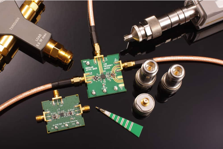
Low POWER TRANSMITTER DESIGN Transmitters perform three basic functions: generate an RF signal, modulate it, and drive it onto an antenna with a PA. Methods for increasing PA efficiency at low power output and reducing overhead power (PoH,rx) needed for RF signal generation and modulation will now be discussed. i mw 2.5 1 75 1 1 oov 1M We will start by briefly introducing the LNA. 1.2 LNA Introduction. Let's start our tutorial with the LNA introduction. Figure 1.1 shows the basic RF radio system contains a baseband processor, up-conversion Mixer, down-conversion Mixer, Voltage Controlled Oscillator (VCO), Local Oscillator (LO) or Frequency Generating Unit (FGU), pre-driver, driver, final Power Amplifier (PA), coupler

PDF Low Power RF Design for Sensor Networks Circuit Diagram
This book presents the basic techniques available to design low power RF CMOS analogue circuits. It gives circuit designers a complete guide of alternatives to optimize power consumption and explains the application of these rules in the most common RF building blocks: LNA, mixers and PLLs.