Home Automation using Arduino and WiFi Circuit Diagram This Arduino code is designed to control a relay using a momentary button. It includes debouncing logic to ensure the button press is stable before triggering any action. Step-by-Step Explanation. 1. Read Button State: int reading = digitalRead(buttonPin); - Reads the current state of the button pin (`HIGH` or `LOW`). 2. Reset Debouncing Timer:
When the temperature crosses the predefined max temperature value mentioned in the Arduino code the relay 1 and the relay 2 turns on. When the temperature becomes lower than the predefined min temperature value mentioned in the Arduino code the relay 1 and the relay 2 turns off. LDR Control. An LDR is fitted on the PCB to sense the ambient light. 2.Connect the power supply and set up the project. Then connect the control pins. Finally connect the load (circuit board that you'll control using a relay module). 3.Power up your arduino using a power supply or USB cable. 4.Write the code. One code example is as follows: // Define the Arduino pin connected to the relay module control pin A relay permits you to easy control "high" voltage appliances, by high voltage I mean 110VAC/220VAC, depending on your relay type, it's module that will permit you to control lights, lamps and other appliances in you house in case you want to make things automated or programmed and controlled by your Arduino. Using a relay module is far

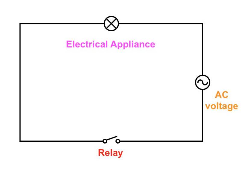
Relay Module with Arduino: A Comprehensive Guide Circuit Diagram
The simplest solution for on/off Home Automation is to use the free pfodDesigner to design your control for upto 4 switches and then use a Arduino Uno + Cheap/Simple Wifi Shield + DFROBOT Relay Shield for Arduino V2.1 powered by a USB power supply and controlled by pfodApp and, if switching mains power, have an electrician wire it in.

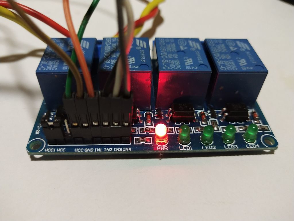
Connecting LDR to Arduino UNO. Connect the A0 analog pin of Arduino to any pin of the LDR. Connect the other pin of the LDR to the 5v of Arduino.; Then connect the 10k resistor from GND to A0 of Arduino.; Connecting Relay to Arduino UNO. Connect the digital pin 8 of Arduino to the Signal pin of the relay module.; Connect the 5v from Arduino to the Power connection of the relay module. When the Arduino sends a signal to the relay, the electromagnet activates and changes the state of the relay's contacts, either turning a device on or off. Use cases of Relay Module. Relays are commonly used in home automation to control high-power devices: Lighting Control: Turn lights on/off remotely or based on sensor inputs. You can use a 5V relay to switch the 120-240V current and use the Arduino to control the relay. * A relay basically allows a relatively low voltage to easily control higher power circuits. A relay accomplishes this by using the 5V outputted from an Arduino pin to energize the electromagnet which in turn closes an internal, physical switch to