Future technology design of water purification based on the CAB a The Circuit Diagram Hello friends, in this video I have shown you how to create a Smart Filter. When you take a glass in front of this filter, the glass will automatically fill

Let's get started with how to build a smart Water Quality Monitoring System using TDS sensor and ESP32 or Arduino. A TDS (Total Dissolved Solids) Sensor measures the total amount of dissolved solids in a liquid, typically water. Dissolved solids include inorganic salts and small organic substances. The measurement is expressed in parts per million (ppm) or milligrams per liter (mg/L).

Tutorial: How to Design Your Own Custom STM32 Microcontroller Board Circuit Diagram
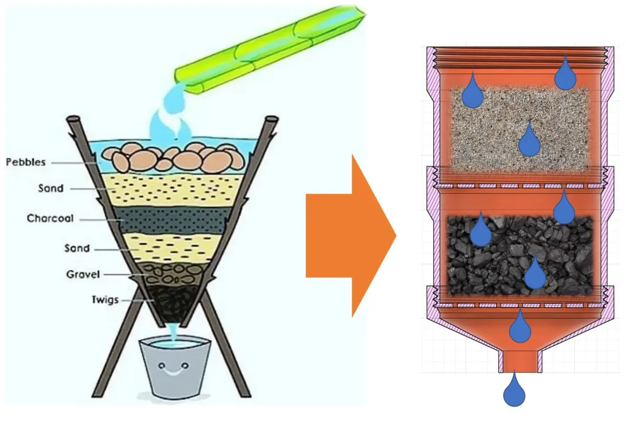
Micro-controller Based Rainwater to Potable Water for Household system is consists of water reservoir, water filters, UV lamp, sensors, pump and pipes in order to create this complete system
Testing water tube. I used an old test tube I had to make this. I poked holes on either end of the tube and inserted wires from either end. Finally, to hold the wires in place, I attached some putty.

Water Quality Monitoring System: TDS Sensor + ESP32/Arduino Circuit Diagram
water quality monitoring- In this tutorial, you will learn how to use Arduino, pH sensor, Nodemcu esp8266 wifi module and Blynk Framework to build an IoT based water quality monitoring system. As this is a project based on the IoT "Internet of Things," you can track water quality from anywhere in the world. In this episode, I will explain Wash the probe with distilled water, then absorb the residual water-drops with paper. Insert the pH probe into the standard buffer solution of 7.0, stir gently, until the values are stable. After the values are stable, the first point can be calibrated. Input enterph command in the serial monitor to enter the calibration mode.

Step 1 - System / Preliminary Design. When developing a new circuit design the first step is the high-level system design (which I also call a preliminary design). Before getting into the details of the full schematic circuit design it's always best to first focus on the big picture of the full system.

Arduino Water Quality Monitoring System Circuit Diagram
To develop an Arduino-based microcontroller system for water quality monitoring and control. The system consists of a multimedia filter arrangement and pipework design to purify water on one-way process flow. Filtered water from all filters flows through a common pipe. During the backwash process, the water level in the filter vessel falls In the next step, an HTML page for this Water Monitoring System using IOT is created as shown below, which has an HTML table to show pH value, Temperature, and soil moisture. The HTML page is stored in a string variable so that it can be sent back on client request using the server.send() function. This paper presents a proposed system to maintain water quality so that it is suitable for human use and reduce water waste by an employee the Arduino microcontroller, and sensors to design an automation system of water pollution monitoring, the design of the system involves the development of the process of monitoring physiochemical parameters
