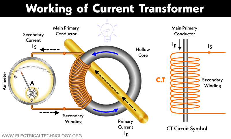
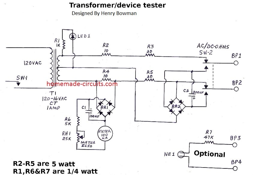
Electrical Transformer Circuit Diagram Three-phase, also written as 3-phase or 3φ type supplies are used for electrical power generation, transmission, and distribution, as well as for all industrial uses. Three-phase supplies have many electrical advantages over using single-phase power. But when considering the use of 3-phase transformers we have to deal with three individual alternating voltages and currents differing in phase Learn how transformers work on the principle of electromagnetic induction and mutual induction to transfer electrical energy between two or more circuits. See diagrams and examples of single-phase transformers, turns ratio, and voltage transformation. Dot notation is used with schematic diagrams to express which terminals are positive at the same instant in time. Figure 3 illustrates how dot notation can be used to identify the Hi and Xi leads. A transformer wiring diagram can be found printed on the transformer nameplate or inside the cover to the wiring compartment. The leads or terminals

Transformer is a device that transfer electrical energy from one alternating-current circuit to another circuit or multiple circuits. Transformer works on the principle of electromagnetic induction. Transformers either increase AC voltage (Step-up transformer) or decreases AC voltage (Step-down transformer). According to the diagram below Learn how to identify and draw transformer symbols in circuit diagrams with different types, configurations and phase shifts. See examples of air-core, iron-core, ferrite-core, power, step-up, step-down and other transformers.

Single Phase Transformer Connections Circuit Diagram
Key learnings: Three-phase Transformer Connections Definition: A three-phase transformer connects its primary and secondary windings in star or delta configurations for various electrical applications.; Star Connection: In star connection, three windings connect at one end to form a neutral point, used for creating a neutral terminal.; Delta Connection: In delta connection, windings form a Ultimately, circuit diagrams of transformers demonstrate one of the greatest aspects of electrical engineering: that pure science can be used to create practical solutions. They show us how abstract principles such as magnetism and induction can be applied in real-world applications, connecting us to the useful applications of electricity. Learn about the ideal transformer, a hypothetical model of a transformer with zero winding resistance, leakage flux and core losses. See the schematic diagram and the equations for voltage, current and impedance transformation.
