Easy Way To Build Circuits In Matlab Wiring Draw And Schematic Circuit Diagram Use the RF Budget Analyzer app for designing RF transmitters and receivers using data sheet parameters. You can subsequently perform full circuit envelope or time domain simulation on your RF system using an rfsystem System object™.. Design RF filters, matching networks, or circuits with arbitrary configurations using RF circuit elements.

Learn how to design and simulate electrical circuits in MATLAB®. Follow an example of designing a simple resistor, inductor, and capacitor (RLC) circuit usin

MATLAB Central Circuit Diagram
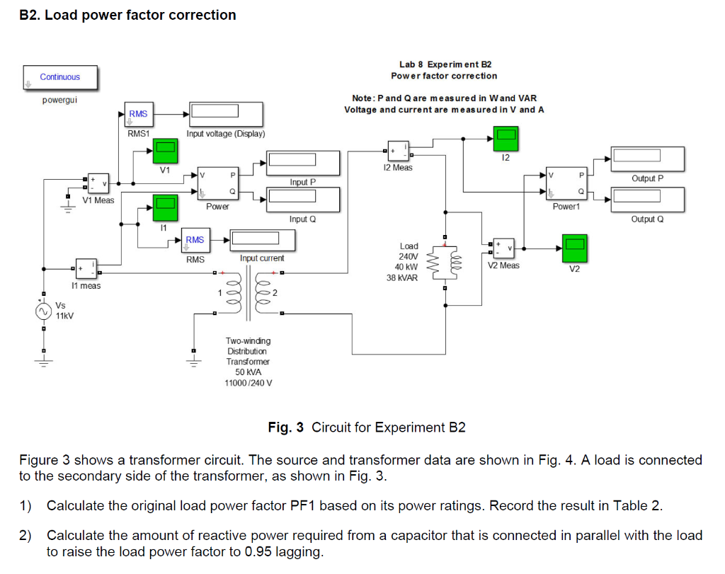
MATLAB is a valuable platform for circuit analysis, enabling you to understand and optimize the behavior of electrical circuits. With MATLAB, you can design and simulate circuits for a variety of engineering applications. Explore the world of circuit analysis in MATLAB to gain insights into electrical systems and their performance! The circuit in the figure represents an equivalent power system feeding a 300-km transmission line. The line is compensated by a shunt inductor at its receiving end. A circuit breaker allows energizing and de-energizing of the line. To simplify matters, only one of the three phases is represented. Learn the basics of simulating analog electric circuits in Simscape. Use the physical network approach to simulate electrical filters and faulty power supplies, and analyze their performance in the time and frequency domains.

This example shows how to build and simulate a simple circuit and view the results. You model a classic circuit configuration consisting of an integrator and a noninverting amplifier to generate the triangle wave. You use datasheets to specify block parameters and then look at the voltage at the wave generator output.

Build and Simulate a Simple Circuit Using Specialized Power Systems Circuit Diagram
Goal is to design/implementation, testing, and verification Electric Circuit problems using MATLAB Simulink Simscape and Live Scripts to understand the concept better. Module 1: Node Analysis Use the node-voltage method to solve a circuit that containing resistors and independent and dependent current sources and voltage sources is connected

Designing and Implementing Circuits in MATLAB and Simulink. Once you have a theoretical understanding of circuit design and analysis, the next step is to implement and test your designs using MATLAB and Simulink. This section provides practical guidance on how to use these tools effectively to simulate and validate your circuit designs. I use MATLAB quite a bit for circuit analysis. Sometimes I prefer it to spice, other times I prefer spice, depends on my mood and requirements. These are the following steps: 1: take the Laplace transform of the circuit ; 2: obtain the transfer function ; 3: plot/analyse using MATLAB functions. bode, impulse, freqresp and so on.

Build and Simulate a Simple Circuit Circuit Diagram
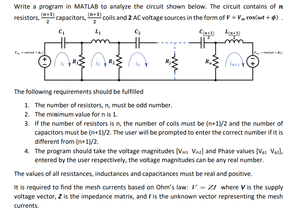
You can use it to add interconnects, modify the values of components, and even create logic blocks for enhanced circuit control. The third popular way to draw circuit diagrams in Matlab is through a script-based approach. With this method, engineers can programmatically specify the components of their circuit and the connections between them