DIY Audio Switch 9 Steps with Pictures Circuit Diagram The circuit requires an operating DC voltage of 9V to 12V. Applications and uses: Sound-activated switches are designed to provide a mechanism through which one can turn on or off any electrical appliance remotely through sound. It could be great for blind people as they don't need to find the switch. It can also be used in toys for children.
Schematic of the sound activated switch circuit. When you first connect the supply voltage to the sound activated switch circuit, the relay will be energised because of the effect of capacitor C2. Allow a few seconds for the relay to be switched off.
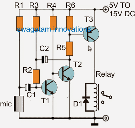
Sound Activated Switch Circuit Circuit Diagram
Want to build your own sound-activated device?In this video, we'll guide you through the process of building a sound-activated relay switch. This DIY electro This circuit is operating on 9-12V DC. The working of this circuit is quite simple, the main component is an audio amplifier LM386 IC. Following are the steps that you should follow to make this circuit work, Sound is received by an Electret mic which converts these sound signals into electrical signals. Sound activated switch. This is Sound activated switch Circuit with PCB using IC-1458 and SCR-C106D. It will work only if the loud is overdue. Ideal for player cameras Or you can bring it to other users. It's not Fouls, such as You may also be applied to a Burglar alarm circuit effectively, or applied to the alarm clock, when it has sounds
Full circuit diagram and parts list can be found here: https://www.homemade-circuits.com/simplest-sound-activated-relay-switch/The video shows the test resul The Circuit. An electret microphone is a type of condenser (capacitor) based microphone that converts sound energy to electrical energy. It is a low cost microphone that can be found in every cellphone, laptop, camera, and so on. The main component of the circuit is the electret microphone and it is used as the sound sensor.
Activated Gadget: A DIY Electronics Project ... Circuit Diagram
A sound sensor switch is a type of switching device that responds to an audio input. With a proper sound-activated switch, dynamic control by sound may be very useful, not just on robotic systems but also for home automation, for example, a sound-activated light responding to a knock on the door or a hand clap.So, in this project, we will build a simple sound sensor switch using the LM393N Hence the sound operated switch circuit reacts swiftly each time a signal is at first obtained, however the relay will not cut out during the brief pauses that take place while in regular speech. The consumption of circuit's quiescent current is just around 250 uA, however this increases to around 35mA once the relay is triggered. 1) Circuit Objective. Utilizing this basic sound activated switch design, toggling a system by a sound pulse could be done very effectively, not only with a robotic system but as well as for any desired of home automation.. As an illustration the circuit could be used like a sound-activated light bulb to illuminate a porch light in response to a knock on the front door.