Diy 350 Watt power inverter circuit with AC 50hz output Circuit Diagram A power inverter is a power electronic device that changes direct current (DC) to alternating current (AC). An inverter converts the DC voltage to an AC voltage. In most cases, the input DC voltage is usually lower while the output AC is equal to the grid supply voltage of either 120 volts, or 240 Volts depending on the country. There are A power inverter circuit is a circuit that converts DC power to AC power. You can make the AC power be any level that you want and to any frequency that you want. etc. Obviously these go beyond the scope of a basic begineer power inverter circuit and would be overkill for a beginner. This circuit is meant to be a first step to creating an

An inverter which uses minimum number of components for converting a 12 V DC to 230 V AC is called a simple inverter. A 12 V lead acid battery is the most standard form of battery which is used for operating such inverters. you are probably all set to create your simple power inverter circuit using these components. The basic design of the

How to Build a DC to AC Power Inverter Circuit Diagram
An inverter's primary function is to convert DC electricity to AC power. The public utility can provide AC electricity to houses and companies; the alternating-power systems or circuits of the batteries only store DC power. Furthermore, practically all everyday appliances, as well as other electrical equipment, can be operated with AC power. Simple Dc to Ac Inverter Make : It's very easy to made DC to AC inverter circuit. This inverter circuit convert DC power to AC power. It can be different value and different power. I will show you convert 12v DC to 220v ac. It will give output about 35 watt. We can get more outpu…
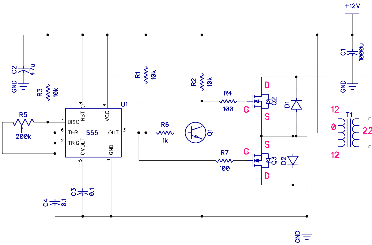
Fig. 1 - Circuit diagram for making Inverter at home. Theory behind the circuit. The circuit of this inverter is dissimilar when compared to the commonly used inverters as it does not have involvement of a separate oscillator circuit to power up the fitted transistors. Power inverters range from simple DIY circuits using a few transistors and a transformer, to expensive commercial units using microcontrollers to generate PWM sine waves. We are going to build a power inverter that takes its input power from a 12V battery, and outputs a 110V/230V AC current. The circuit is outlined in the block diagram The maximum power of this inverter depends on the size of the transformer and the input power supply. The frequency of this circuit is around 60 to 70Hz and the efficiency of this circuit is around 63%. So guys that is all for this project. Thankyou! Watch Full Step by Step video --> Full Video. Check out our Youtube Channel -->creativElectron7M
