Designed circuit arrangement of frequency to voltage converter Circuit Diagram Project Build - 555 Timer Voltage to Frequency ConverterSubscribe to the channel: https://www.youtube.com/channel/UCNt-VKnOf-6-vVYqdiI_K8g?sub_confirmation= Output Frequency: The output is a frequency signal, typically a pulse train, where the frequency is directly proportional to the input voltage. Voltage to Frequency Converter Circuit. Now here we will show the how to design a voltage to frequency converter circuit and explain how the circuit works. Here two LM358N op-amps are used, the first This frequency voltage converter circuit using IC 4151 is characterized by its highly linear conversion ratio. With the indicated part values the conversion ratio of the circuit can be expected to be around 1 V/kHz. When a DC voltage is used at the input having 0 Hz frequency, the output generates a corresponding voltage of 0 V.

The output frequency can be easily adjusted with the help of U1 voltage. D3 diode is required because we want to eliminate R4 and P1 influence. D1 and D2 diodes produce a small flow of temperature. With P2 we adjust the offset voltage. Because of its high quality, this voltage-frequency converter (VCO) can be used in a large field of applications. Making a frequency to voltage converter - All you need to know Description LM331 is basically a precision voltage to frequency converter from National Semiconductors. The IC has a hand full of applications like analog to digital conversion, long term integration, voltage to frequency conversion, frequency to voltage conversion. Wide dynamic range and excellent linearity
PDF MT Circuit Diagram
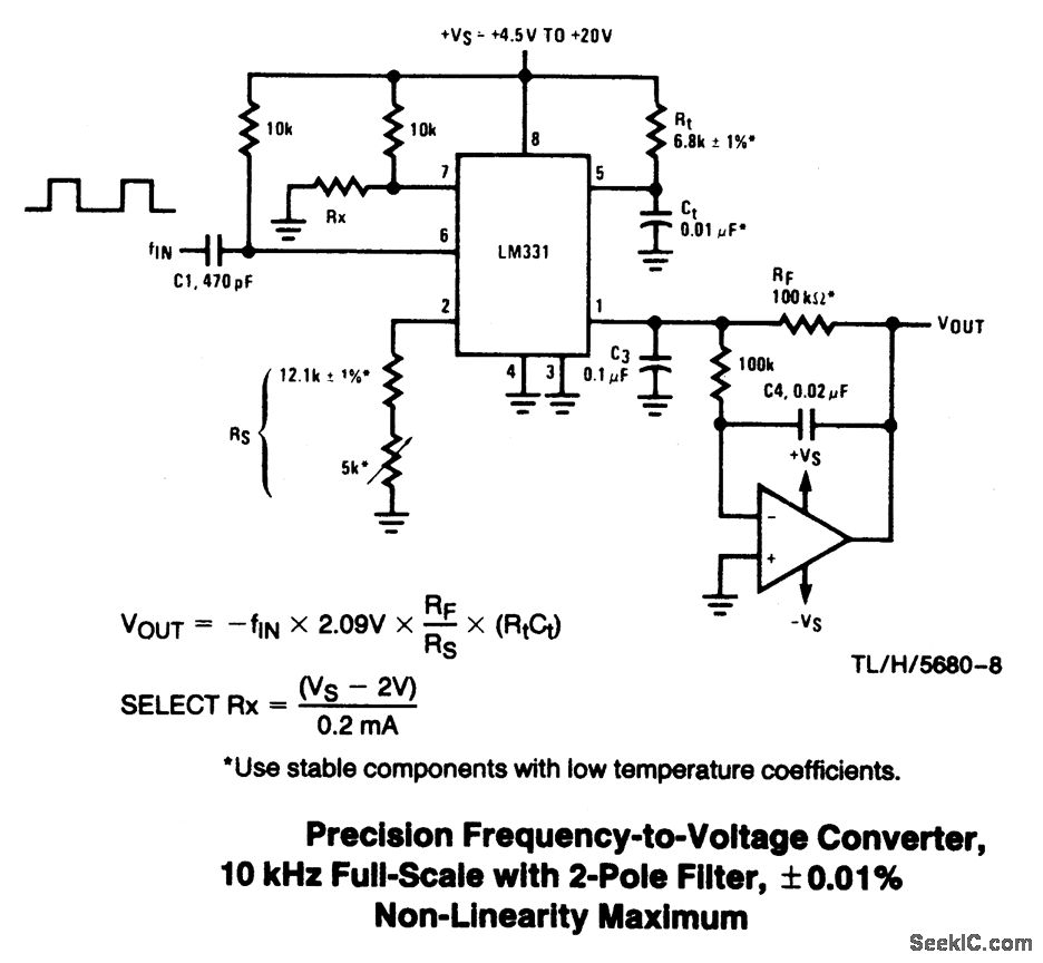
Want to develop your own voltage to frequency converter? Yes, it's possible. And not too difficult.Watch this video to see the proof-of-concept. Plus, get to The next high performance frequency to voltage converter circuit is built around a few components and an IC based switching circuit. With the part values indicated in the schematic, the ratio of conversion is achieved with a linear response of approx. 1%. When an input voltage from 0 V-10 V is applied it gets converted to a proportionate A voltage-to-frequency converter (VFC) is an oscillator whose frequency is linearly proportional to a control voltage. The VFC/counter ADC is monotonic and free of missing codes, integrates John L. Lindesmith, "Voltage-to-Digital Measuring Circuit," U.S. Patent 2,835,868, filed September 16, 1952, issued May 20, 1958. (voltage-to-frequency