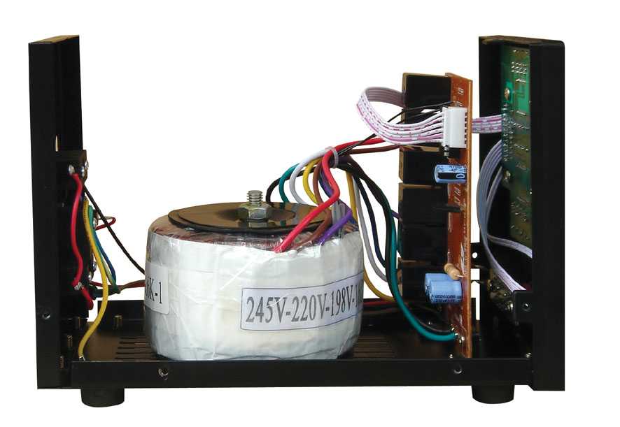
Choosing the right Voltage Stabilizer for Your AC Features and Circuit Diagram Automatic voltage stabilizer (AC-AC) with PIC16F873A - circuit, explanation, PCB, source code, videos and loads of pictures! February 16, 2014 Tahmid. We at Enertech also brings Voltage Stabilizers for the clients that are widely accepted for providing constant voltage even under unbalanced electric conditions. Our stabilizers are

The write-up subtly states a Simplest Mains Voltage Stabilizer Circuit which may be constructed by every new hobbyist for custom-made utilization. So if the input AC voltage has a tendency to boost a set threshold value, the transformer deducts some voltage and tries to quit the voltage from achieving harmful levels and vice versa during First and foremost, an ac voltage stabilizer circuit is designed to maintain a consistent output of voltage. This is done by using an adjustable voltage regulator to ensure that any input voltage fluctuations are accounted for and regulated. The most important component of an ac voltage stabilizer circuit is the voltage regulator itself.

SCR/Triac Controlled Automatic Voltage Stabilizer Circuit Circuit Diagram
Here I am presenting some Most using and popular automatic stabilizer circuit diagram. 3 relay stabilizer circuit diagram. These are the following schematics diagrams of most using stabilizers. you can troubleshoot or construct a stabilizer by using the following circuit diagrams. this circuit diagram includes 2-relay, 3-relay with IC and without IC and with high voltage auto cut.

voltage stabilizer SENSING OF INPUT VOLATGES. First of all, a bridge rectifier is used to convert the input AC voltage into DC voltage, followed by a large capacitor which smoothes out the DC voltage. And by using a voltage divider circuit we step down the DC voltage so that the microcontroller can accept it.After long speculation and A voltage stabilizer is a device which is designed to sense inappropriate voltage fluctuations in AC mains supply inputs, and correct them to produce a stabilized voltage for the connected appliances or gadgets. How the Circuit Functions

Automatic Voltage Stabilizer Circuit using SCR/TRIAC Circuit Diagram
At voltages lower than 170 volts and higher than 300 volts, this triac-controlled AC voltage stabilizer will cut off. IC 4093 Internal Gate Pinout Arrangement Parts List. The following components are needed to build this SCR control ac voltage stabilizer: All resistors are ¼ Watt, CFR 5%, unless otherwise stated. In this article we're going learn how we can create a two-relay, or two-stage, mains AC voltage stabilizer circuit. This handy little setup will help us control and regulate 220V or 120V mains voltages using a pretty straightforward circuit design.

The present circuit of triac controlled AC voltage stabilizer is outstanding in its performance and is almost an ideal voltage stabilizer in every respect. As usual the circuit has been exclusively designed by me. It is able to control and dimension the input AC mains voltage accurately through 4 independent steps.
![[SOLVED] How AC voltage stabilizer works Circuit Diagram](http://obrazki.elektroda.pl/2537329900_1451881525.jpg)