Bridge DC Motor Driver Circuit Diagram The end goal of this project is to use this DIY H-Bridge Motor Driver to prepare a small Micro Robot concept. In this Instructables, you will learn about how the Motor Driver works and how we can construct a simple H Bridge circuit for making our own Motor driver IC, so Let's get started. Supplies. Perf Board; Arduino Nano; BC547 SOT23-3

Because, the single transistor motor driver was able to control the speed of motor. But, unable to control direction of the motor. So, We need a H bridge of transistors in order to control speed as well as direction of the motor efficiently. Also, This motor driver dose not cost any more than $1.25 USD making it super cheap. Here, for further driving current the two channels were parallel. if the frequency is higher the gate driver has to be stronger. The SPDT switch is used to choose the H-bridge leg that controls the path. H-Bridge is the circuit's functioning component, which controls the motor. The pulldown resistor usually pulls the MOSFET gates down low.
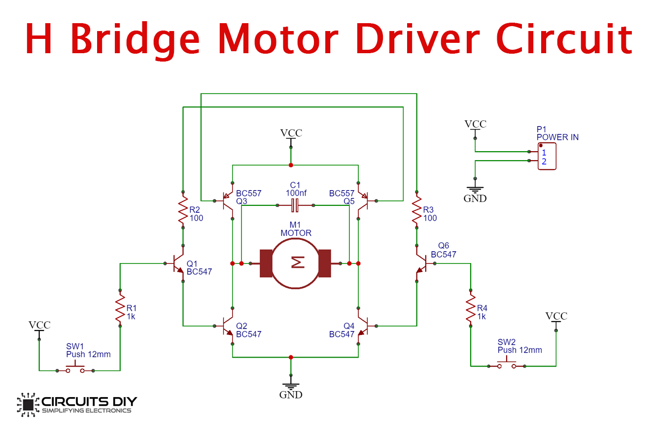
Simple H Bridge Motor Driver Circuit Diagram and Working
The H-Bridge Motor Driver Circuit . This circuit is called H-bridge because the MOSFETs form the two vertical strokes and the motor forms the horizontal stroke of the alphabet 'H'. It is the simple and elegant solution to all motor driving problems. The direction can be changed easily and the speed can be controlled.. In an H-bridge configuration, only the diagonally opposite pairs of

Read Also: Many about transistor driver circuits. Bridge transistor Motor driver. As Figure 5, we use the four transistors to connected into the H-bridge circuit. Figure 5: we use the four transistors as a switch controller. And add a diode to protect the electricity that may flow backward from the motor. Making damage to the transistor. The following things fall under consideration while creating H-Bridge motor driver circuit: Electrical Noise. During the working of the H-Bridge motor driver circuit, the motor can make noises and can damage the MOSFETS. So it must be kept in consideration. Shoot through. Shoot-through means that the two MOSFETS are on at the same time.
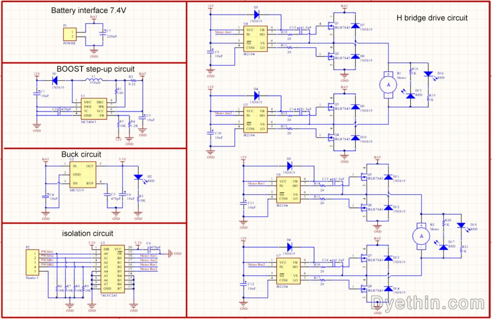
Bridge Motor Driver Circuit using MOSFET Circuit Diagram
It is widely used in robotics and motor control applications. This article outlines how to build an H-bridge motor driver circuit using IRFZ44N MOSFETs as the main switching elements, BC547 transistors for driving the complementary MOSFETs, and the required resistors and switches (S1 and S2) to control motor direction. and a simple Here, a DC motor driver comes into play. A motor driver is an integrated current amplifier circuit that is capable of acting as a bridge between the controller and the DC motor in a motor drive. So in today's tutorial, we are going to go over a step by step procedure on How To Make An H-Bridge Motor Driver Circuit Using L293D IC. The H-Bridge is a circuit which can drive a DC motor in forward and reverse. The motor direction is changed by switching the polarity of the voltage in order to turn the motor one way or the other. This is easily demonstrated by applying a 9-volt battery to the leads of a small motor and then switching the terminals to change directions.