automatic street light circuit diagram Archives Circuit Diagram 1. Automatic Street Light Control System.(Sensor using LDR & Transistor BC 547.). We have tried and Cicuit#1 in this tutorial but you may also try the second one (Circuit#2) mentioned below ight after circuit no 1.
We'll attach a relay to the setup and a light bulb in our next circuit to illustrate how to improve the circuit to perform actions such as lighting a bulb. Run Code After setting up your circuit as above, you must upload a control code .
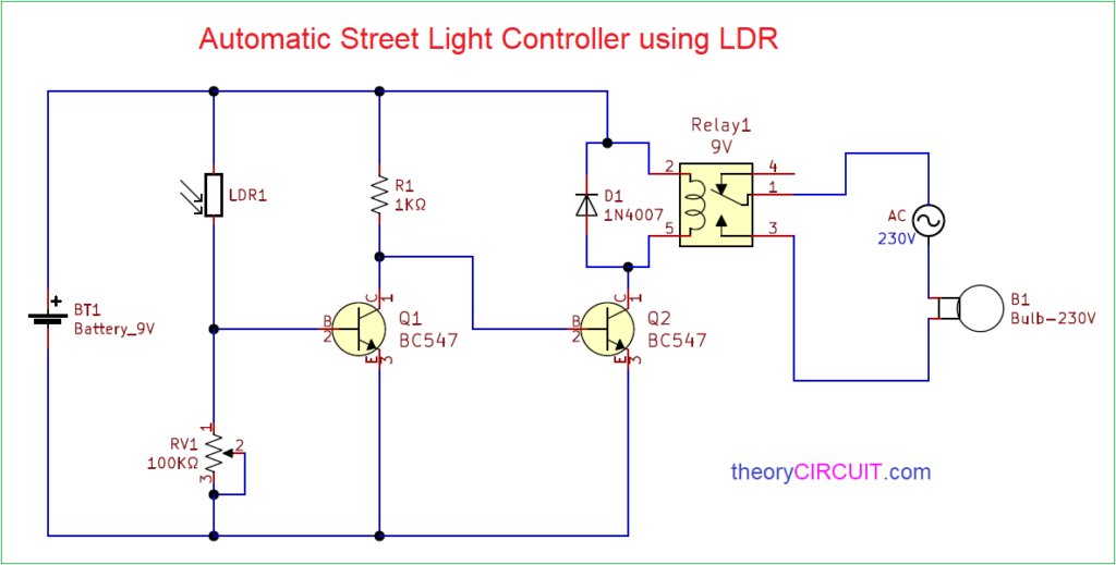
Automatic Street Light Control Circuit using LDR & Transistor Circuit Diagram
Automatic Light Circuit Diagram with Fixed Trigger Threshold Automatic Light Circuit with Adjustable Trigger Threshold Building the Automatic Light Circuit. The LM741 IC is housed in a 8-pin DIP, so normal DIP IC pin numbering applies to it. If using a bright LED, place the LED away from the LDR. A photo of the completed breadboard circuit is

Automatic Street Light Controller Circuit Design: Automatic street light controller are devices or systems designed to control the operation of street lights based on predefined conditions. They play a crucial role in managing the energy consumption of street lighting, improving overall efficiency,… The circuit can be used as a commercial automatic street light control system, as a domestic porch light or corridor light controller or simply can be used by any school kid for displaying the feature in his school fair exhibition.The following content describes four simple ways of making a light activated switch using different methods.. 1) Light Activated Day Night Switch using Transistors In this project, we use relay for controlling AC light because the Arduino cannot control high volt , but a relay can do this job, which is the sole design of it. so we are using relay as switch to control high power devices. There are two ways to assembly the relay connection : 1. NC = Normally Closed Connection ( which I'm going to use ). 2.
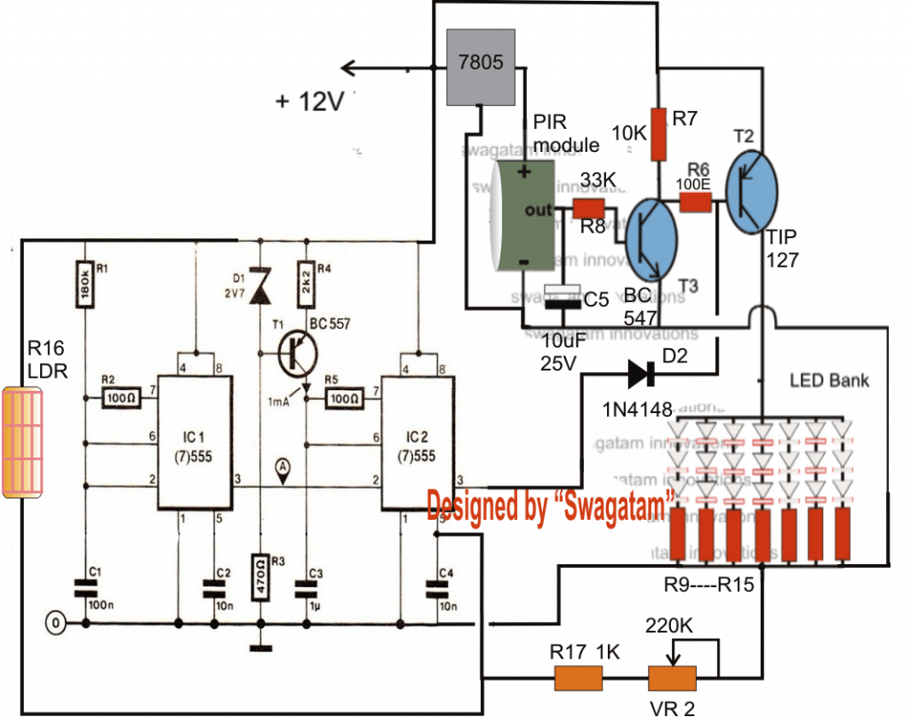
4 Automatic Day Night Switch Circuits Explained Circuit Diagram
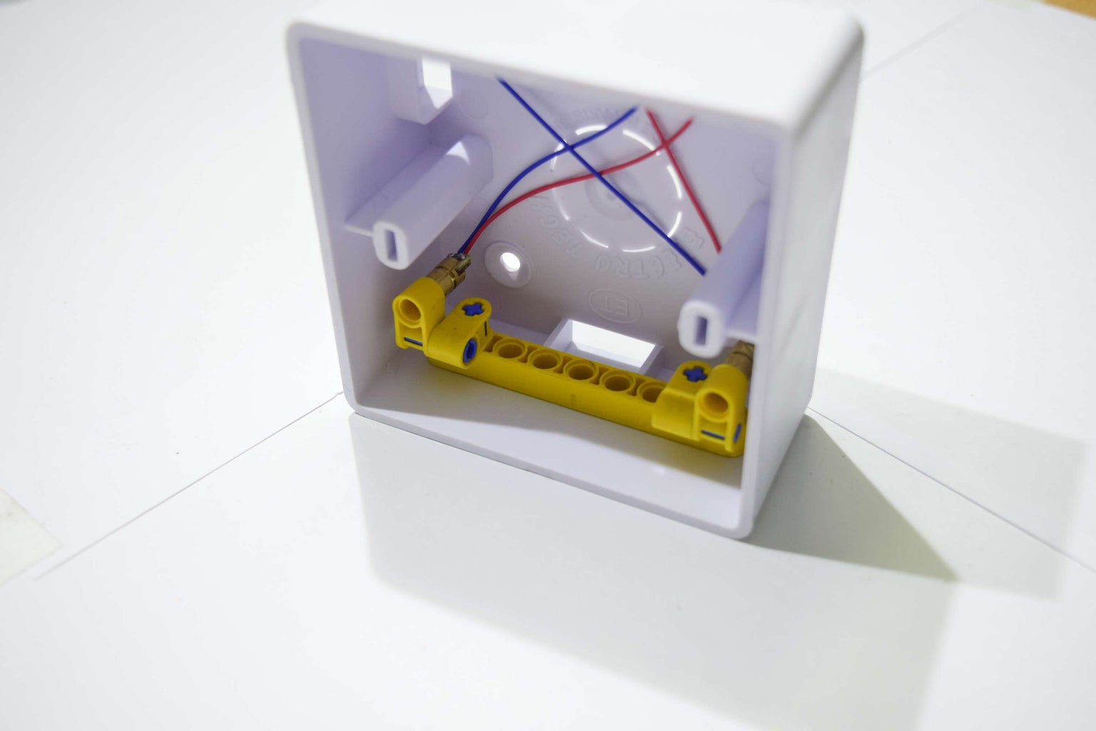
Drill holes in the project box to mount the electronic circuits. The ldr circuit will be mounted such that it faces the lasers. The arduino will be mounted in the center such that you have usb access. Insulate and add the relay module in there. My box was small so it was a tight fit. I couldnt mount the relay module. How The Night Light Circuit Works. The photoresistor and the 100 kΩ resistor make up a voltage divider. When there is a lot of light, the photoresistor will have low resistance, which means the voltage divider gives a low output voltage. So the transistor is off and cuts off the current to the LED. Which means no light. How the Night Light Circuit Works: The automatic night light circuit operates based on the principle of the light-dependent resistor (LDR) and transistor control. In darkness or low-light conditions, the LDR's resistance is high, preventing current from flowing through the base of the transistor.