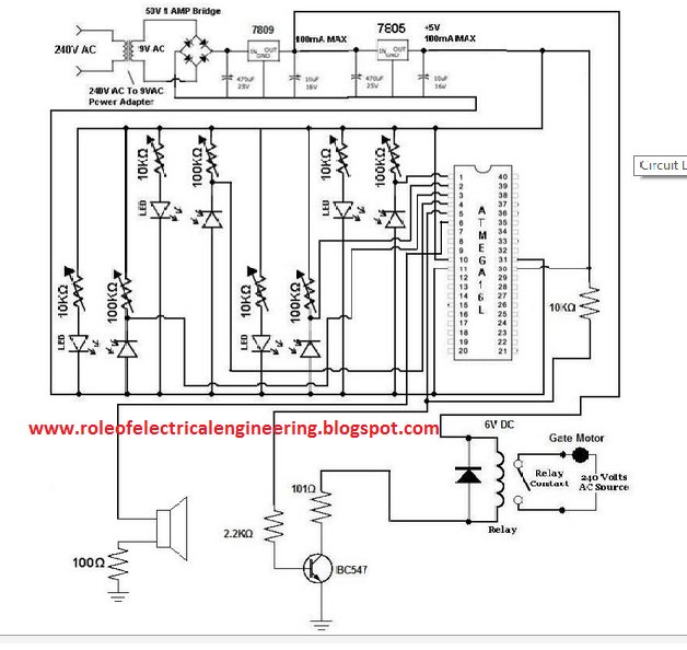
AUTOMATIC RAILWAY GATE CONTROLLER USING ARDUINO BOARD Circuit Diagram The automatic railway gate control system with Arduino is a technology-based system that ensures the safe passage of trains by automatically controlling railway crossing gates. Using infrared sensors and an Arduino, this system operates automatically without human intervention, improving efficiency and preventing train accidents. The Automatic Railway Gate Control System using IR Sensor & Arduino focuses on systematic traffic control of railway gates that are both manned and unmanned. This project will not only make the system more reliable & precise, but also save the authorities from hiring man power to do the job. You may take it as a onetime investment. This video explains how you can make your own automatic railway gate control system by using simple components like an ultrasonic sensor, servo motor, evive-

To design an automatic railway gate control by using microcontroller. Furthermore, this project is aimed to replace the gatekeepers with an automatic system. It is develop to apply the structure of interfacing program in between to give a lot of advantages. Automatic Railway Gate Control System Project - PCB Design for IR Sensor Pair Automatic Railway Gate Control System is a simple but very useful project, which help is automatically opening and closing the railway gate upon detecting arrival or departure of the train. In general, Railway gates are opened or closed manually by a gate keeper. Design of Basic Logic Gates using NAND Gate; Universal gates-NOR Gate;
How to Build an Automatic Railway Gate Control Using Arduino Circuit Diagram
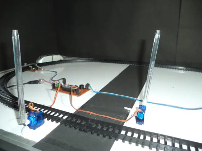
In this tutorial, we will learn how to design a simple and efficient automatic high-speed railway gate controller system. This is a relatively simple approach to this project but you can take this as a basic building block and in further modification we can also track the speed of the train with which it passes and so much more. Operator Control Systems: If you choose manual operation, design an interface that allows operators to monitor train schedules and control the gates effectively. Automated Systems: For an automated setup, consider using a microcontroller (like Arduino) to manage the inputs from the sensors and control the gate mechanisms. Make connections according to the above diagram. Connect Arduino's 5V pin with the VCC pin of both the IR sensors and the positive wire of the servo motor. Connect the Arduino's ground pin with the ground(GND) terminal of both the IR sensors and the negative wire of the servo motor.The output(OUT) terminals of both the IR sensors are connected to the digital 2 and 3 pins of Arduino.