Automatic Fan Control System Circuit Diagram Temperature Based Fan Speed Control & Monitoring With Arduino: In this post, we have described how to design Temperature Based Fan Speed Control & Monitoring With Arduino and LM35 Temperature Sensor. The microcontroller controls the speed of an electric fan according to the requirement & allows dynamic and faster control and the LCD makes the several electronic components is designed and implemented for automatic fan speed control. An LCD display is used as an optional feature to display temperature and fan speed. Finally, the developed system circuitry was tested many times and worked very well. Keywords:Fan speed, microcontroller, LM35DZ, BLDC motor AND circuit design. I. INTRODUCTION This project is an independent design of an automatic fan speed control system based on the variation of room temperature by using the Arduino microcontroller and DHT11 temperature sensor.
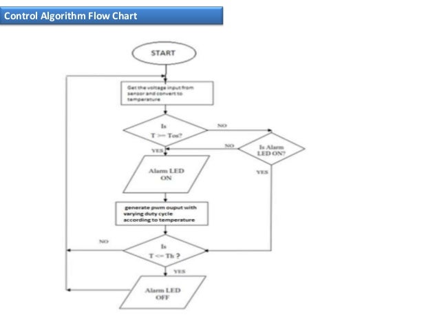
This microcontroller has inbuilt PWM module which is used for controlling the speed of the fan by changing the duty cycle. Fan Speed Control System using PIC16F877A Microcontroller. According to the temperature sensor readings, the duty cycle will be automatically changed for controlling fan speed. The microcontroller will send the PWM signal The document describes a project to control the speed of a fan using a microcontroller based on temperature readings from an LM35 temperature sensor. It uses an ATMEGA32 microcontroller to read the analog output from the LM35 sensor, convert it to a digital value, and generate a PWM signal to control the speed of a brushless DC motor fan. Automatic control plays an ever-increasing role in a person's lifestyle. Automatic control is a vast technology area with a central focus on developing control strategies that increase productivity when applied to a system. A distinctive feature of automatic control is that it reduces the number of people-operators. One such gadget is a fan. Fans are usually available with variable speed
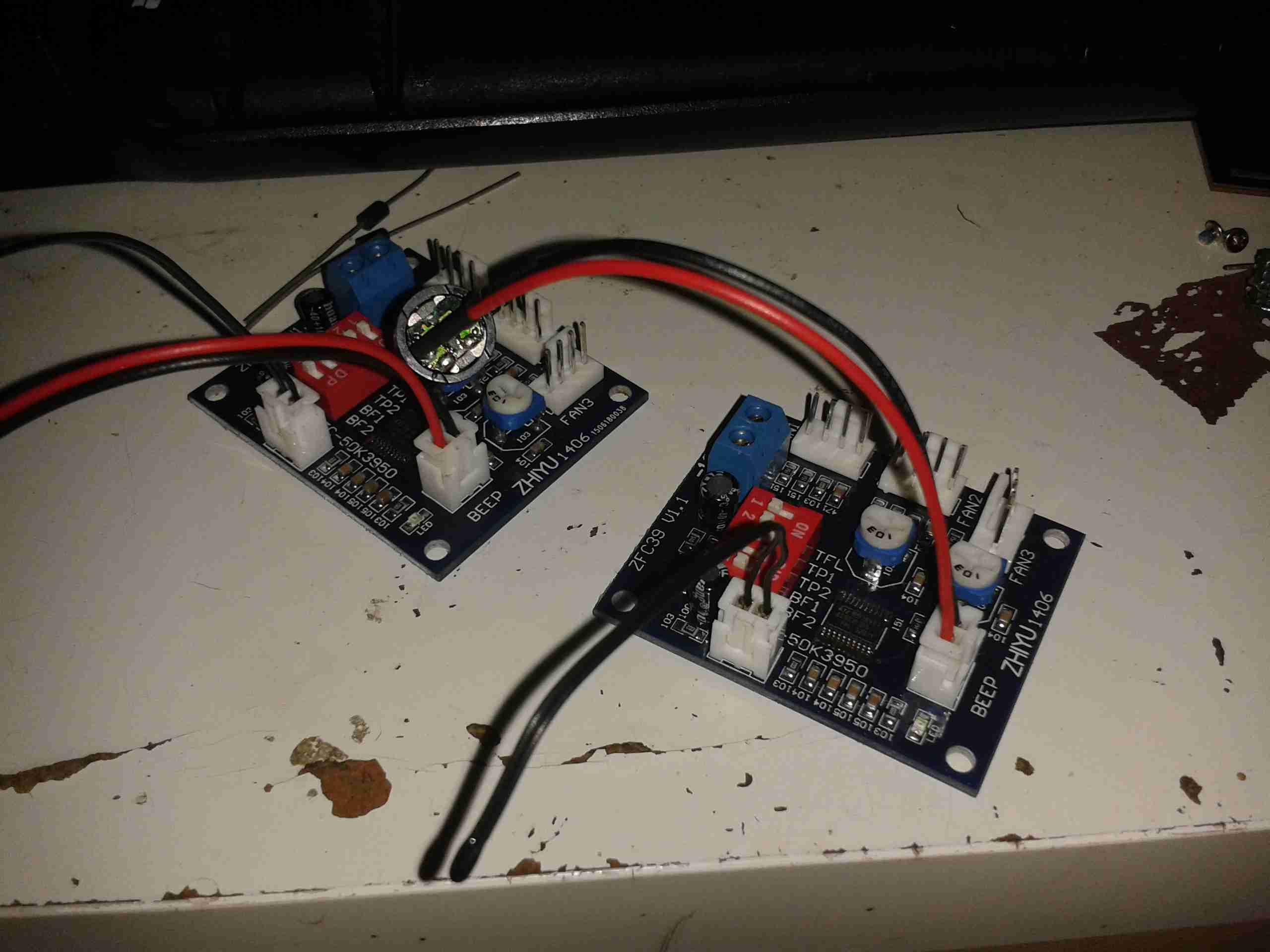
Automatic Fan Speed Control System Using Microcontroller Circuit Diagram
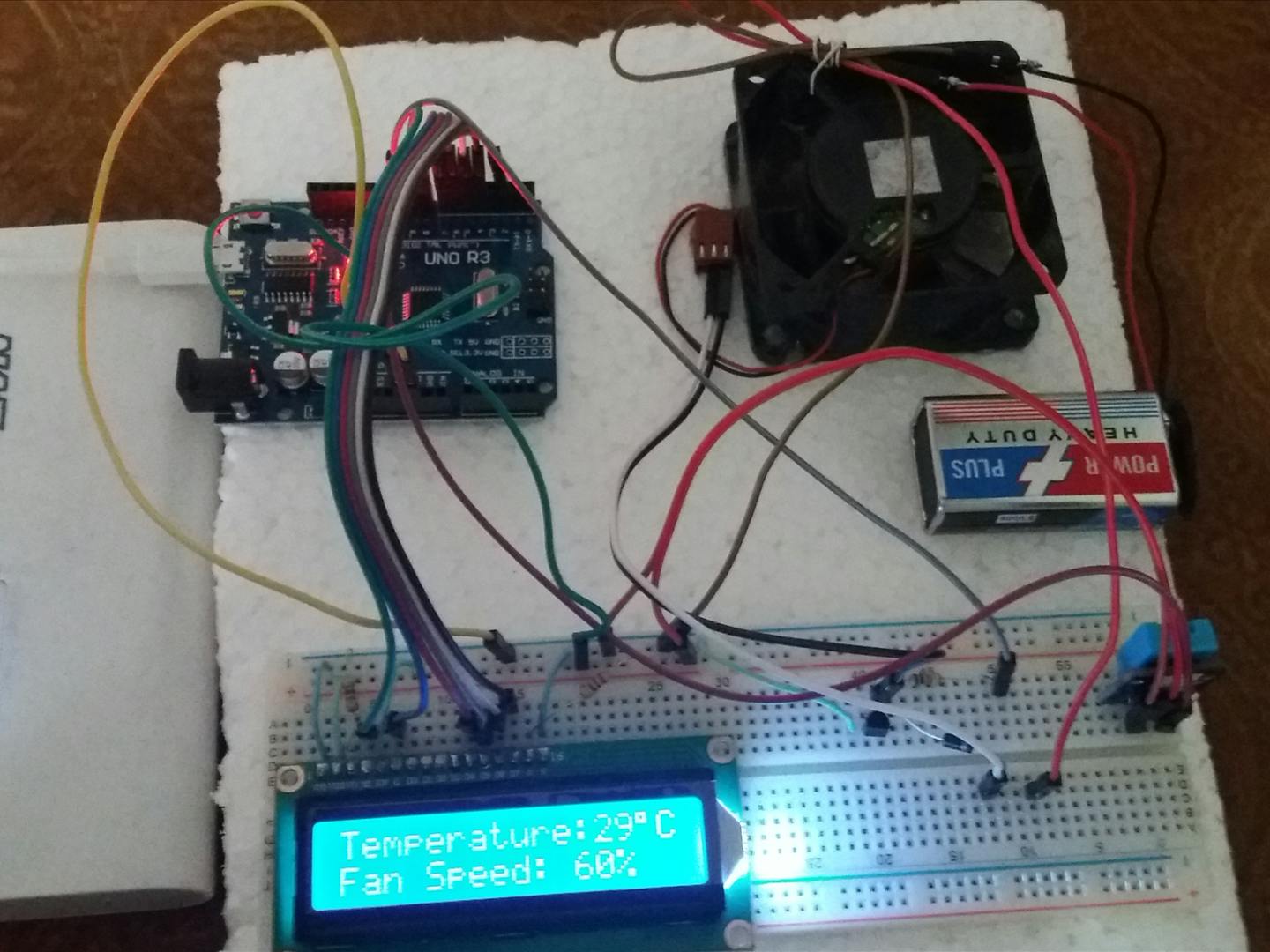
inconveniences associated in changing the Fan speed level manually when the room temperature changes. So, an efficient automatic Fan speed control system that automatically changes the speed level according to the change in environment / room temperature was implemented to solve the problems associated in Fan speed manual control The 2N2222 NPN transistor acts as a controller switch which controls the speed of the fan by using the signal from the Arduino. The IN4007 Diode acts as a protection for the fan from being damaged. When the temperature exceeds the max temp the 5mm LED light glows. Working of the temperature based fan speed controller Circuit

Automatic Fan Speed Control System Using MicrocontrollerPlease Subscribe For More Project Videos -- http://bit.ly/29vPrS9Slice-- http://www.svskits.in/ blog