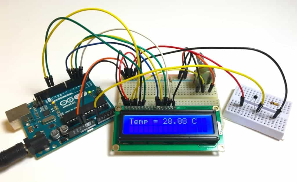
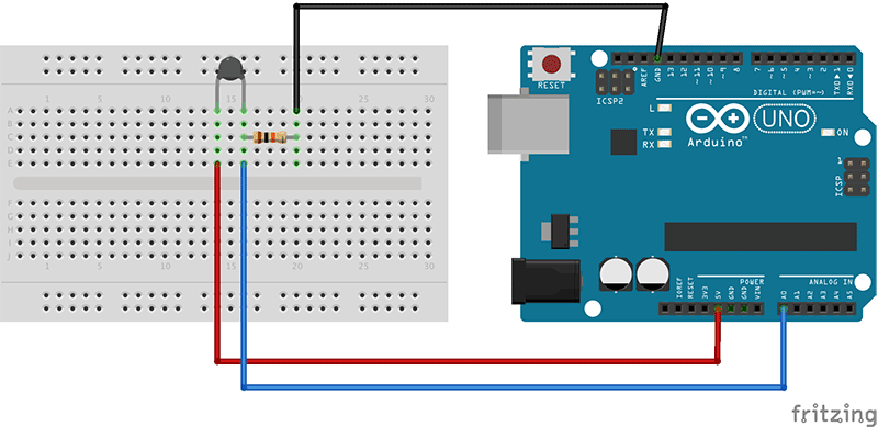
Arduino temperature sensor Circuit Diagram The typical TMP36 temperature sensor's operating range is (-40°C To 125°C). TMP36 Arduino Wiring (Circuit Diagram) Here is the wiring diagram for Arduino with the TMP36 temperature sensor. Note that I'm using the A0 analog input pin to read the analog output voltage of the TMP36 temperature sensor. TMP36 Arduino Code Hello to everyone, a little help please? I want to build a thermistor temp sensor using arduino (as in above circuit) but then need to convert measured temperature in degrees centigrade to air flow in meters per second, and be able to display on screen, and record this via computer. Any help suggestions greatly appreciated. regards Andrew Wiring - Connecting LM35 analog temperature sensor to Arduino Connecting an LM35 to the Arduino is very easy as you only need to connect 3 pins. Start by connecting the +V S pin to the 5 V output of the Arduino and the GND pin to the ground.
Learn how to use temperature sensor with Arduino, how to connect DS18B20 temperature sensor to Arduino, how to program Arduino step by step. The detail instruction, code, wiring diagram, video tutorial, line-by-line code explanation are provided to help you quickly get started with Arduino. Find this and other Arduino tutorials on ArduinoGetStarted.com. The IC we will use to measure the temperature is the TMP36 IC. We will integrate this with the arduino to measure the temperature. The arduino will then read this measured value from the TMP36 and translate into degrees fahrenheit which we will be able to read from the computer. Components Needed to Build Temperature Sensor Circuit. Arduino Board
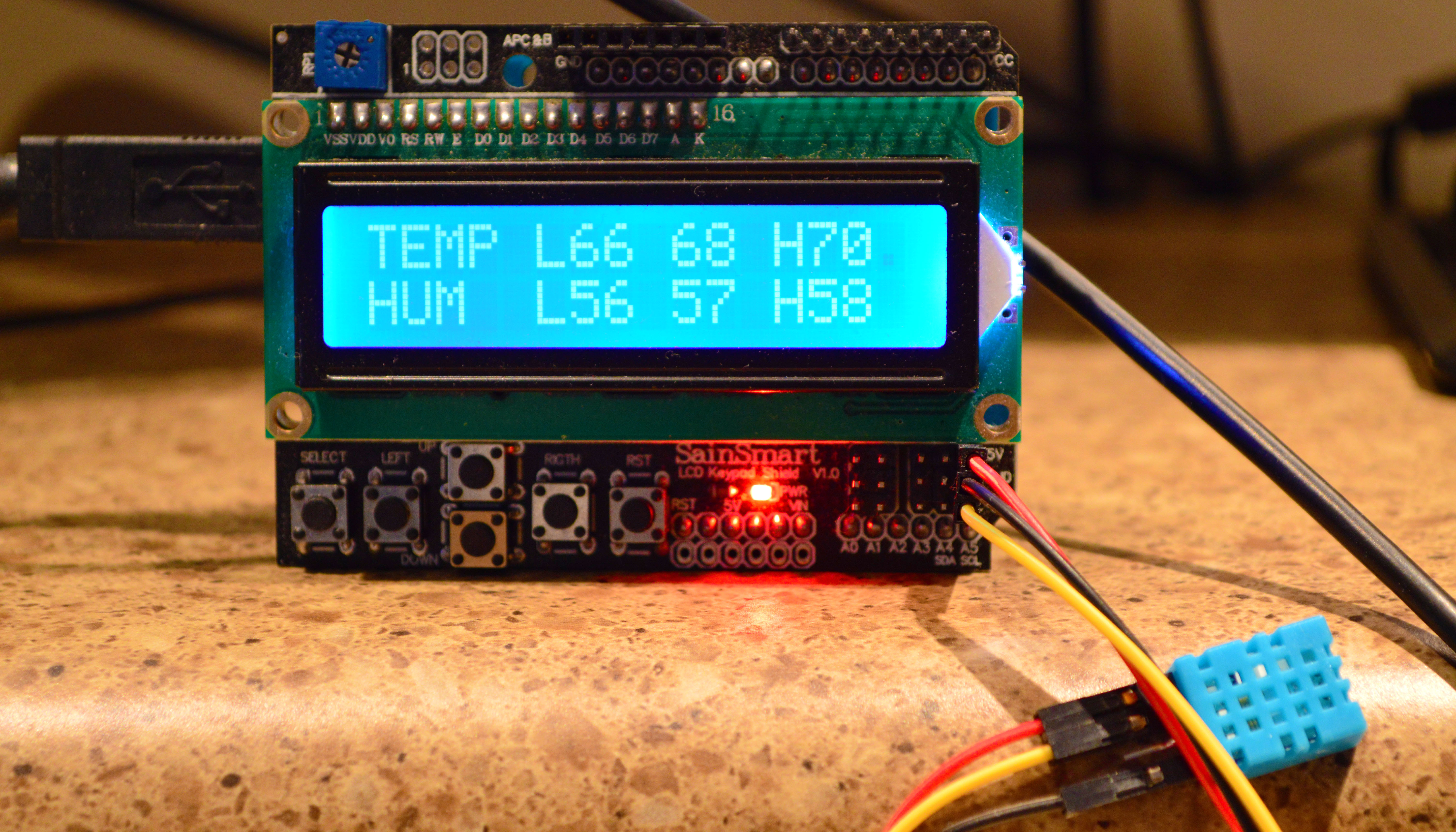
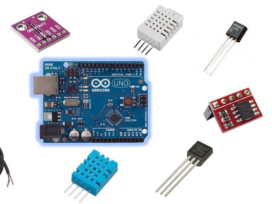
Temperature Sensor With Arduino UNO Circuit Diagram
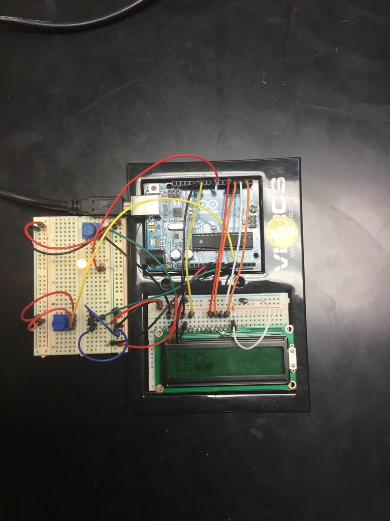
With the following example code, you can read the temperature from a DS18B20 sensor and display it in the Serial Monitor. You can upload the example code to your Arduino using the Arduino IDE. To copy the code, click on the button in the top right corner of the code field. /* DS18B20 1-Wire digital temperature sensor with Arduino example code. The DS18B20 temperature sensor and the 16×2 Arduino LCD module are popular components for this task, and interfacing them with an Arduino UNO microcontroller makes it possible to build a compact, low-cost, and highly customizable temperature monitoring system. Simple Temperature Sensor Circuit using LM35 IC. Abdul Wadood. 29,934 views
Arduino - Temperature Sensor circuit. Pin 1(DC voltage): This pin is used for setting up the DC voltage pin to 5V on the Arduino UNO board. Pin 2(Analog voltage output): This pin is responsible for generating the output of the measured temperature.
TMP36 With Arduino Temperature Sensor Code & Tutorial Circuit Diagram
Temperature Sensor With Arduino UNO: Learn how to read Temperature using LM35 Temperature sensor! The LM35 series are precision integrated-circuit temperature devices with an output voltage linearly proportional to the Centigrade temperature. The LM35 device has an advantage over linea…