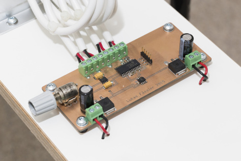
Arduino nano with PWM LED DIMMER CIRCUIT Circuit Diagram The circuit shows a 36 LED (1 watt each) light strip bank being driven by the PWM and the current controller stages. The LED series resistors are introduced for safeguarding each 3 LED string from over voltage. since the total forward voltage drop of the strings constitute to 3.3 x 3 = 9.9V and the supply voltage 12V that's about 2V higher.

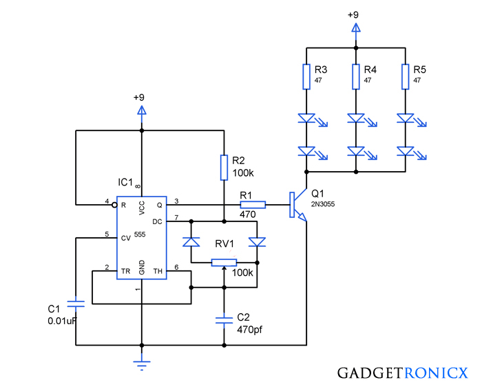
The generated PWM Signal is then applied to a bunch of LEDs and based on the Duty Cycle of the PWM Signal, the intensity of the LEDs can be high or low. Related Post: LED Lamp Dimmer Circuit. A Brief Note on 555 Timer IC. The 555 Timer is an 8-pin Integrated Circuit available in Dual-in-Line Package originally developed by Signetics.
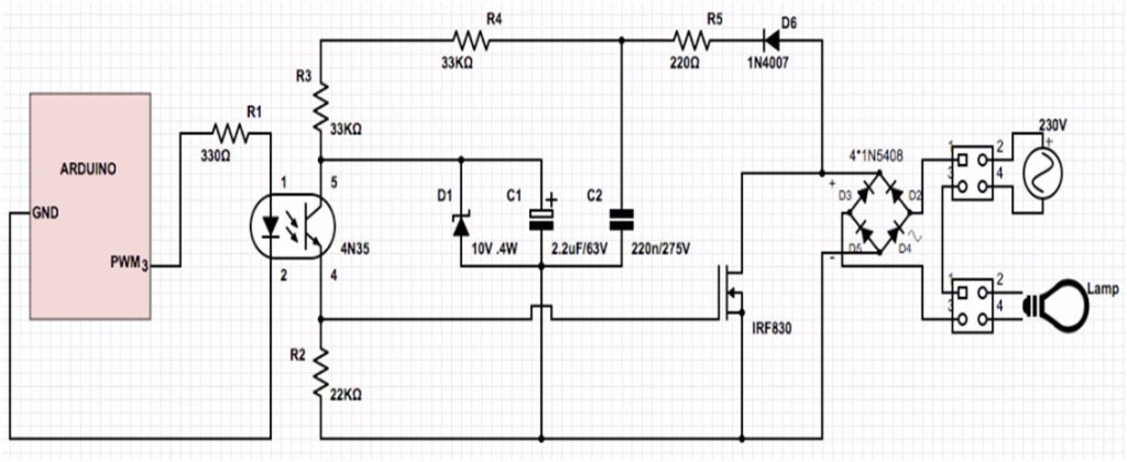
Simple Arduino LED Dimmer Circuit using PWM Circuit Diagram
In this video, I demonstrate how to build a simple yet effective PWM (Pulse Width Modulation) circuit using the versatile 555 timer IC. This circuit allows y This LED dimmer is built around the CD 4093 CMOS chip.PWM technique (pulse width modulation) is a very efficient way of controlling the brightness of LEDs with minimum energy waste.Instead of varying the brightness by varying the supply current with a variable resistor or transistor it is accomplished by varying the ratio of ON time vs OFF time.This when done at a high frequency rate is This video shows how you can make a PWM control circuit with just a few components. The circuit uses the 555 Timer IC and has several applications such as an
It is easy to use PWM on Arduino setting up PWM on ATMEGA is harder, as you need to adjust many settings. Arduino already has these settings ready, so you can use PWM easily by calling the right functions. On the LED pin, the Arduino microcontroller produces a square wave signal. The resistors and capacitor filter the square wave to create a DC I hope you have understood how to use the control pin#5 of the IC 555 to create a varying PWM output and a varying DC lamp illumination. Power Supply can be 12 V DC. This DC light dimmer circuit can be operated from a 12 V DC power supply. However, the operating voltage of the circuit will depend on the specifications of the lamp.
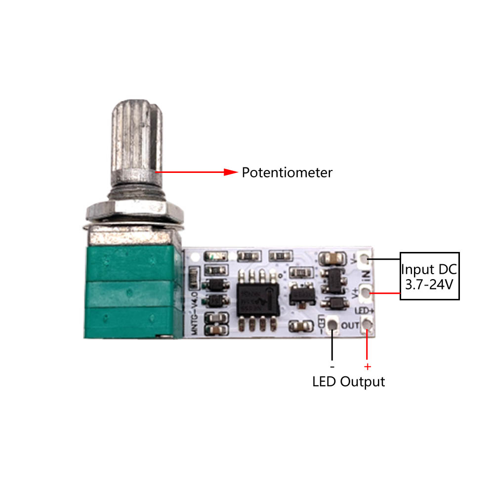
Arduino LED Dimmer (Potentiometer + PWM) Circuit Diagram
So, in this article, we will make a 12V PWM lamp dimmer using NE555 IC and a few switching transistors and diode. You can also make Light Dimmer using MOSFET and 555 Timer or a DC Motor Speed Control project based on PWM. The 555 Timer-based circuit is only valid for DC circuits over a small voltage range. You cannot use this circuit with AC To make an Arduino LED Dimmer project, you need to use a PWM output pin and an analog input pin (for the potentiometer) 1- Set an IO pin as an output pin using the pinMode function. 2- Continuously read the analog input pin for the potentiometer 3- Map the 10-Bit ADC reading to the range of the 8-Bit PWM's duty cycle and write the value using