Arduino Frequency Counter Circuit Diagram In CRO we use f=1/T formula to calculate frequency.Here also the same concept is used to calculate frequency. where. T is the time period of one cycle of signal in microseconds(us) In the program of Arduino Frequency counter we used f=1000000/pulseTotal. Where. pulse Total is nothing but, a Time period of Signal(T). microseconds(us)=10^-6 Note if you are going to use some other source of frequency make sure that you connect (share) the GND with arduino GND. Step 3: Start Visuino, and Select the Arduino UNO Board Type The Visuino: https://www.visuino.eu also needs to be installed. The aim of the project is to design a simple digital frequency counter circuit using Arduino UNO and 555 Timer IC. The working of the project is very simple and is explained here. As mentioned earlier, the 555 Timer IC is configured to operate in Astable mode. Hence, the output of the 555 Timer IC (or rather the signal generator circuit) is a
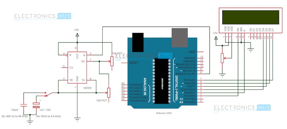
Learning how to make an Arduino frequency counter is incredibly rewarding, both in terms of the satisfaction you get from creating something yourself, as well as the new knowledge you gain. Frequency Meter Circuit Page 4 Counter Circuits Next Gr. Arduino Frequency Counter Tutorial With Circuit Diagrams Code. Arduino frequency counter circuit: Project circuit diagram is shown below. The 16×2 LCD screen (2 rows and 16 columns) is used to display the values of frequency and period of the input voltage where: RS —> Arduino digital pin 2 E —> Arduino digital pin 3 D4 —> Arduino digital pin 4 D5 —> Arduino digital pin 6 D6 —> Arduino digital pin 7 Circuit Diagram of Frequency measurement. It does not require any external components; you may connect pull down resistor of 100k on Pin 2 to avoid noise measurement when there is no input. Measurement is carried out on interrupt 0, Use only Pin 2 of Arduino. Arduino Frequency Measurement Circuit Arduino Frequency Measurement Code

High Frequency Counter With Arduino Guide Circuit Diagram
Frequency Counter With Arduino : This is a simple and cheap arduino based frequency Counter cost less than 4$ it been very useful to measure small circuits. Projects Contests Teachers Frequency Counter With Arduino . By kiran.bholiyan in Circuits Arduino. 8,653. 37. 8. Featured. Introduction: Frequency Counter With Arduino
This is actually a simple counter circuit using Arduino. We can modify this circuit for other applications like tachometer, intrusion counter, etc. Conclusion. Frequency counters are one of the essential test instruments with a wide range of applications. You can easily create one using Arduino with the program and circuit, we have discussed in Electronic counters, also known as frequency counters, use digital circuits to measure the frequency of an input signal. They work by counting the number of cycles or pulses in a given time interval and then calculating the frequency based on this count. Power and Circuit Protection Programmers Passives Sensors and Transducers Semiconductors Test Products Tools Projects 555 Timer Circuits Op-amp Circuits Audio Circuits Power Supply Circuits Frequency Counter using Arduino. Published June 13, 2016 40.