An Integrated Framework for Complex Radar System Design Circuit Diagram Now, grab your Arduino Nano, plug in the USB cable, and upload the code that will make your DIY radar system actually work. The code is fairly long and we have included it at the end of this tutorial.

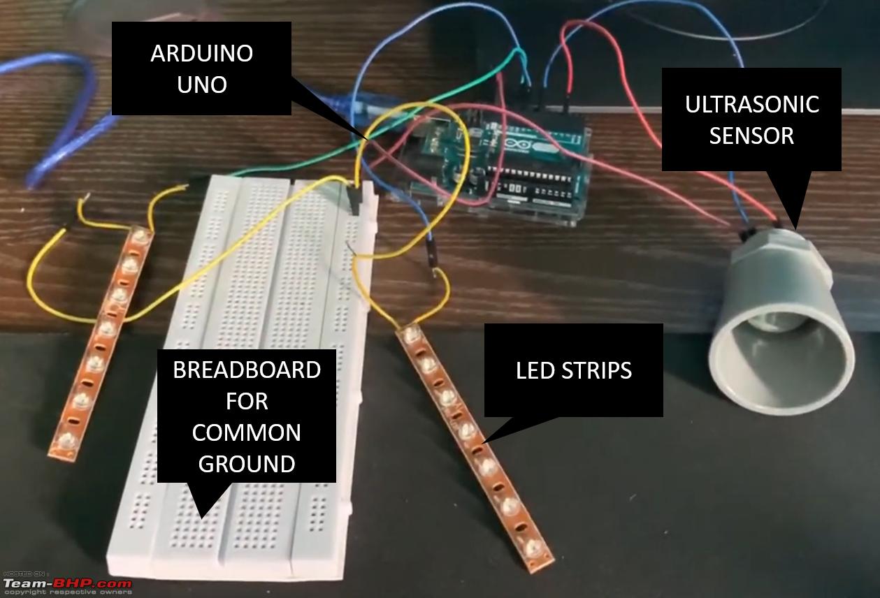
In this project, we will learn how to make a simple radar system with Arduino UNO R4 WIFI board. This is just the basic structure, you can expand and modify it as you like. I used a waterproof ultrasonic sensor to measure distance, which is ideal for getting the best accuracy reading. However, you can also use the HC-SR04 ultrasonic sensor if

Radar Tutorial Circuit Diagram
Are you interested in building and testing your own imaging radar system? MIT Lincoln Laboratory offers this 3-week course in the design, fabrication, and test of a laptop-based radar sensor capable of measuring Doppler, range, and forming synthetic aperture radar (SAR) images. You do not have to be a radar engineer but it helps if you are interested in any of the following; electronics Building Your CW Radar System. With an understanding of how CW radar works, let's walk through the steps of building a basic CW radar system. In this example, we'll use the Phaser Kit, but the steps can be adapted for any of the other hardware options mentioned earlier. Step 1: Assembling the Hardware
Arduino radar allows you to detect objects within a short range. This project is easy and fun to make, obviously. You can use this project for showcasing in school science fair. I have added the video to help making this radar easily. Lets start making it….. Overview. To make this radar we need three basic components.
Array Radar In Your Garage That Sees Through Walls Circuit Diagram
Of course, a simple analog sawtooth generator would fill this job. This has however the disadvantage that the radar can thereby really only this one sawtooth. The radar then cannot be extended to other modulation patterns. Receiver. For the time being, the receiver consists practically only of a small USB oscilloscope.

In this tutorial, we'll walk you through step by step how to assemble the components on a breadboard and how to program the Arduino board. We'll use the Ardu
Arduino Radar : 9 Steps (with Pictures) Circuit Diagram
in this video we learn How to make simple radar system easy at home. its very easy homemade and cheapest project. in this project i use arduino. we try to ex