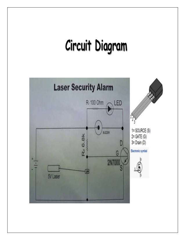
A PROJECT REPORT On LASER SECURITY ALARM SYSTEM Circuit Diagram If your alarm circuit is powered by 4.5 volts (three AA batteries), then it is possible to power the laser pointer from this battery pack as well. All you have to do is connect the terminals of the laser pointer to the batteries of the alarm circuit. One terminal of the laser pointer is a spring that sticks out of the internal circuit board.
A laser-based security system is a type of security alarm that uses a light sensor and laser light. In this tutorial, we are going to demonstrate a circuit of a laser security alarm system that will detect any irregular activity and will produce sound using a buzzer. One of the main components of this circuit is LDR.

Laser Tripwire Alarm : 9 Steps (with Pictures) Circuit Diagram
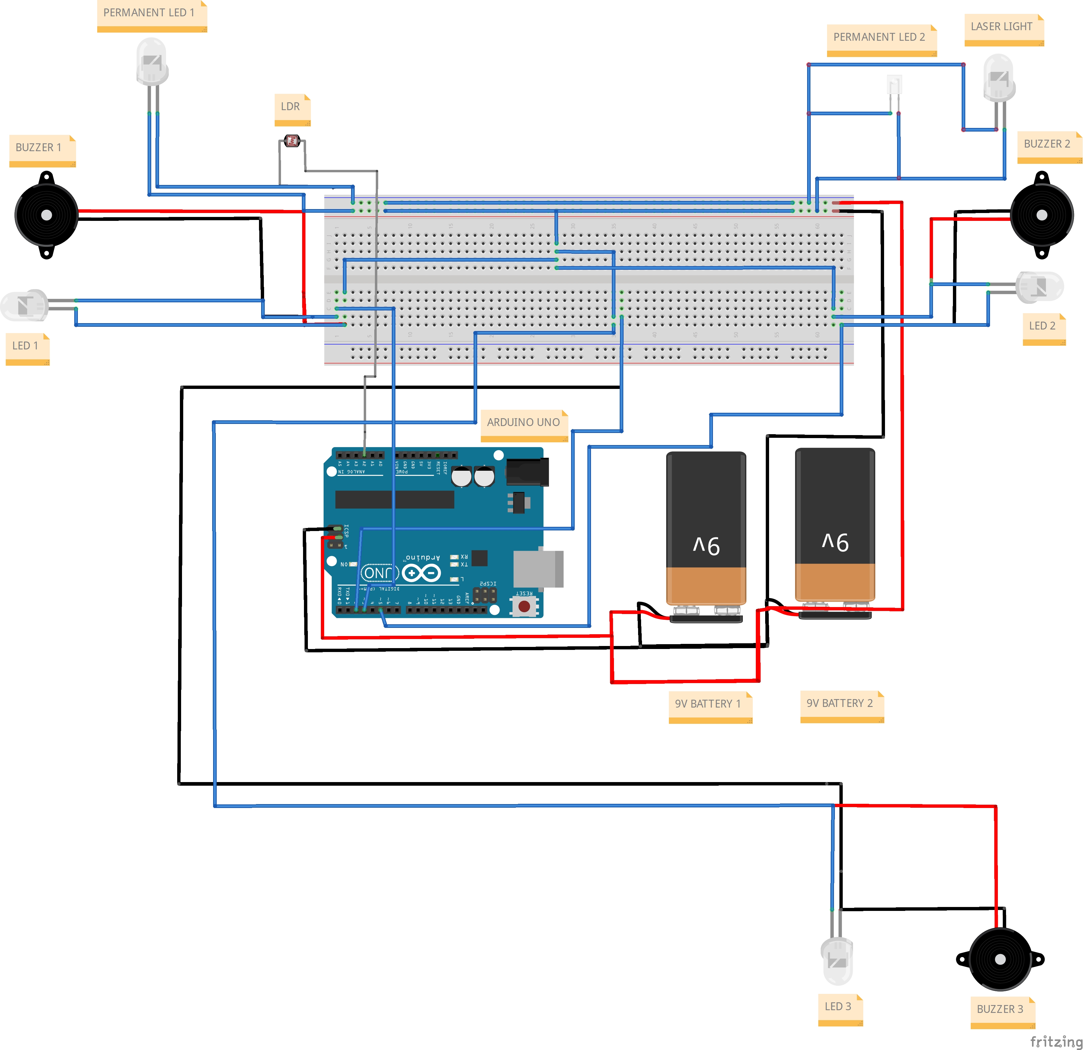
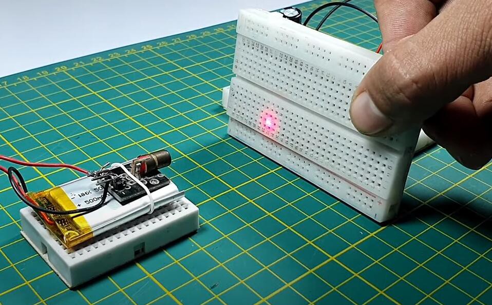
As soon as you connect the battery the L.E.D and buzzer will come "ON" (if you're in a dark room). Focus the Laser diode/light on the LDR and you will see the L.E.D and Buzzer going "OFF" If you interrupt the laser light focusing on the LDR the circuit will trigger and the alarm will ring! Congrats! Your "Laser Security Alarm System" is now ready! Here is a basic idea of how you can make a laser security alarm using an Arduino and an LDR sensor: Materials needed: Arduino board; Laser diode; LDR sensor; Buzzer; Breadboard; Jumper wires; 220 Ohm resistor; Steps: Connect the LDR sensor to the breadboard. Connect the 220 Ohm resistor to the LDR sensor and connect it to the ground pin on the
The LASER-Based Security Alarm is a safety purpose circuit that gives a warning or signal alert when an intruder or invaders try to invade a home, museum, office, bank, or any other place. So, in this article, we are going to make the LASER Security Alarm Circuit. One of the key components is LDR. So, before making the circuit, you just need to
How to make a Laser Security Alarm Circuit Diagram
We know the LASER (Light Amplification by Stimulated Emission of Radiation) light has high strength focused light rays, in this project we have used that laser light as a fence. Laser security alarm circuit produce highly audible buzzer beep sound when the laser light blocked. Here LDR placed to sense the laser light from the laser diode. Because, in this tutorial, we are going to make a "Laser Security Alarm Circuit". Along with the laser, the circuit uses the LDR as its key component. The electrical characteristic of the LDR is where the light increases, and its resistance decreases. Because of the higher resistance, the circuit does not operate until the light falls on
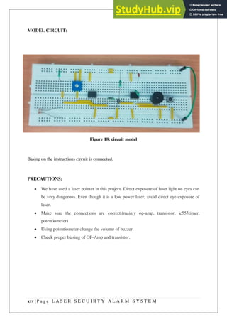
Learn how to make a laser security alarm circuit to protect your home or valuables from theft. This step-by-step tutorial will guide you through the process When the laser pen shines on the photoresistor, the green LED will light up to signify that the circuit is ready. When the laser beam is broken, the LED turns off and the buzzer sounds. As we know from Projects 13 ("Weather Station") and 18 ("Intruder Sensor"), photoresistors produce variable resistance depending on the amount of light Take a permanent marker and make a rough layout or path draw on your PCB as shown in figure 1. Fig. 1: Layout or path draw of the PCB Fig.2: Laser Light Circuit Fig. 3: Schematic Circuit diagram of the laser light security alarm system Step 2. Clean the PCB with the help of a scrubber and after taking a small size container and some PCB etching solution (Ferrous Chloride), prepare a solution