A Novel Secure IoTBased Smart Home Circuit Diagram This paper presents the design and implementation of a wireless-controllable power outlet system for home automation networks. The proposed power outlet module integrates a ZigBee radio into its Key components of IoT home automation. Smart home automation relies on three core elements: devices, communication protocols, and automation platforms. Smart devices. These include thermostats that adapt to your schedule, cameras that monitor your surroundings, and light bulbs you can dim or color-change through an app or voice command. How to Create an Automation Script. What's Next? Key IoT Concepts in this Tutorial. Here are the key concepts related to the Internet of Things (IoT) and smart homes that you'll be working with: Zigbee is a wireless communication protocol used in smart home devices. It relies on a Zigbee coordinator to communicate with devices like lights

An efficient network enhances home automation reliability, improves device response times, and reduces operational disruptions, making smart home management seamless and enjoyable. Studies show that optimized networking can improve device interoperability and user experience (Zafari, Papadopoulos & Christidis, 2016). Control home appliances with WiFi (Blynk App) Control home appliances with manual switches. Monitor real-time feedback in the Blynk App. Control home appliances manually without internet. For each room, you just need a relay module & NodeMCU to make this smart home project.

Building a Smart Home: Expert Guide for IoT Home Automation Circuit Diagram
This smart home project has the following features:1. Home appliances controlled from Mobile using Blynk App 2. Home appliances controlled by temperature & Humidity sensor automatically (In Auto Mode) 3. Home appliances controlled by Dark Sensor automatically (In Auto Mode) 4. Monitor LIVE room temperature & Humidity reading on OLED and

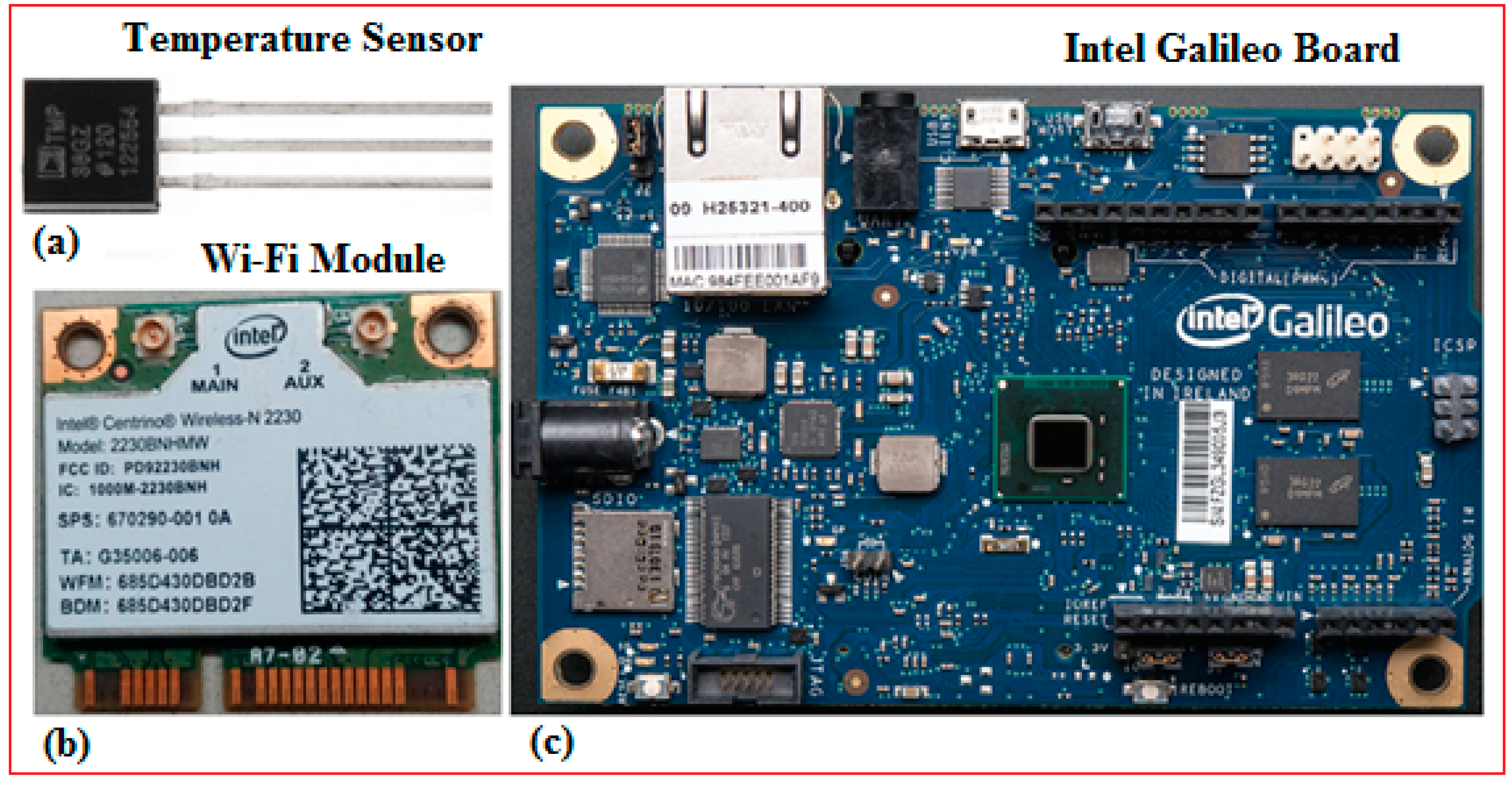
TL;DR Key Takeaways : Zigbee is a low-power, mesh networking protocol ideal for smart home and IoT applications, offering energy efficiency and independence from internet connectivity. Popular In this blog, we'll walk you through the steps to create your own smart home using Arduino and IoT sensors. Step 1: Gather the Required Components. To create a smart home using Arduino and IoT sensors, you'll need the following components: Arduino board (e.g., Arduino Uno) Breadboard. Jumper wires. IoT sensors (e.g., temperature, humidity

How to Build DIY Zigbee Devices for Smart Home Automation Circuit Diagram
4. Exploring the Possibilities of Smart Home Systems - Smart Actions . 1. Essential Hardware Basics . The foundation of any smart home system lies in its network infrastructure and smart devices. Most smart devices rely on WiFi connectivity, although some also support wired connections. With platforms like Home Assistant and OpenHAB, along with Python coding and sensor integration, you can transform your home into a smart, responsive environment. So why wait? Start building your home automation system today, and enjoy the convenience of a smart home that you've created yourself! Frequently Asked Questions. 1.